Gas mixing device for photovoltaic glass sputtering manufacture procedure

A technology of gas mixing device and photovoltaic glass, which is applied in the direction of sputtering plating, ion implantation plating, metal material coating process, etc., can solve the difficult and effective control of film ratio, increase the flow rate of gas filling, and cannot effectively achieve Deposited film ratio and other issues

Inactive Publication Date: 2013-09-11
JIFU NEW ENERGY TECH SHANGHAI
View PDF0 Cites 1 Cited by
  • Summary
  • Abstract
  • Description
  • Claims
  • Application Information

AI Technical Summary

Problems solved by technology

When there are more than two kinds of reactive sputtering gases, if the gas is directly connected to the inlet pipe and then directly charged into the sputtering process chamber, the two gases cannot be fully mixed and will be reacted by the plasma in the process chamber, and the desired sputtering cannot be effectively achieved. The proportion of the deposited film will increase the flow rate of a certain gas, making it more difficult to effectively control the proportion of each molecule in the film.

Method used


Image

  • Gas mixing device for photovoltaic glass sputtering manufacture procedure

Examples


Embodiment Construction

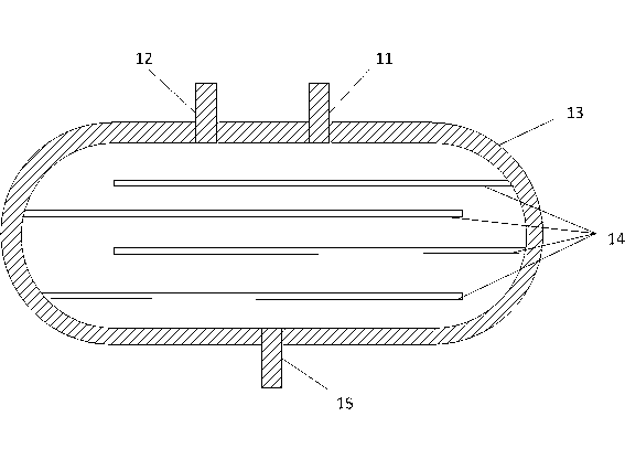
[0013] In order to make it easier to understand other features and advantages of the present invention and the effects achieved, the present invention will be described in detail as follows in conjunction with the accompanying drawings: Please refer to figure 1 The main purpose of the present invention is to provide a gas mixing device for photovoltaic glass sputtering process, which is to connect the stainless steel inner polishing container 13 to the front of the intake pipe through the gas outlet 15 through the ferrule connection tube, and the other end of the stainless steel inner polishing container 13 Then connect the two kinds of reaction gases required by the gas inlets 11 and 12 with ferrules, and 4 gas partitions 14 are arranged inside the stainless steel polishing container 13, with a thickness of 3 mm and a length of 150 mm. There is a distance of 50mm between the plates 14, which are arranged symmetrically in the stainless steel inner polishing container 13, and th...


PUM

PropertyMeasurementUnit
diameteraaaaaaaaaa
thicknessaaaaaaaaaa
lengthaaaaaaaaaa

Abstract

The invention provides a gas mixing device for a photovoltaic glass sputtering manufacture procedure. According to the gas mixing device, a stainless steel internal-polished container is connected to the front side of a gas feeding pipe through a clamping sleeve connection pipe; the other end of the stainless steel internal-polished container is connected with two types of required reaction gas through clamping sleeves; four gas baffles are arranged inside the stainless steel internal-polished container and are 3 mm thick and 150 mm long; a distance between each gas baffle and the wall of the container is 50 mm; a distance between every two adjacent baffles is 50 mm; the gas baffles are eudipleurally arranged in the container and then are welded to be sealed; when the two types of gas are introduced by the gas feeding pipe, under the relation of pressure difference, the gas can move forward along the baffles arranged in the stainless steel internal-polished container; the baffles are eudipleurally arranged, so that the gas traveling path is lengthened; furthermore, the gas has a plenty of time to be fully mixed before being fed into the gas feeding pipe; therefore, a thin film deposited by sputtering can reach a desire mixed reaction proportion.

Description

[0001] Technical field [0002] The invention belongs to the field of gas introduction and mixing devices for photovoltaic glass sputtering equipment, and in particular relates to a gas mixing device for photovoltaic glass sputtering process. Background technique [0003] The invention relates to a photovoltaic glass sputtering process gas mixing device. The reactive sputtering gas introduction device is a key component of magnetron sputtering equipment, and is mainly used to fill the sputtering process chamber with reactive sputtering gas, and then adjust The reactive gas is distributed along the length of the target to obtain uniform thickness of the thin film deposited by reactive sputtering along the length of the target, usually by setting a long gas inlet along the length of the target. When there are more than two kinds of reactive sputtering gases, if the gas is directly connected to the inlet pipe and then directly charged into the sputtering process chamber, the tw...

Claims


Application Information

Patent Timeline
Patent Type & Authority Applications(China)
IPC IPC(8): C23C14/00C23C14/34
Inventor 周文彬刘幼海刘吉人
Owner JIFU NEW ENERGY TECH SHANGHAI
Why Eureka
Try Eureka