High-temperature denitration, fly ash re-ignition and in-furnace dust removal boiler

A boiler and boiler front wall technology, which is applied in the fields of high-temperature denitrification, boiler dust removal in the furnace, and fly ash reburning. It can solve the problems of inability to achieve denitrification effect, decrease in combustion efficiency, and high urea concentration, so as to reduce the escape concentration and prolong the travel time. path, the effect of prolonging the reaction time

Pending Publication Date: 2019-07-09
马成果
View PDF0 Cites 0 Cited by
  • Summary
  • Abstract
  • Description
  • Claims
  • Application Information

AI Technical Summary

Problems solved by technology

[0004] At present, the commonly used method of spraying urea to reduce NOx is to spray urea liquid on the top of the furnace or in the flue of the rear heating surface, that is, the flue in the front area of ​​the economizer, for denitrification. This method has a low temperature for the reduction reaction (far from the optimum temperature 800-950°C), the reaction time, space, and path are limited and the escaped NOx and urea concentrations are high so that the ideal denitrification effect cannot be achieved, and the water generated during the reaction and the water in the urea liquid will wet the soot particles , it will cause severe sticking and dust accumulation on the heating surface at the tail of the economizer, which will block the heat exchange in the light case, and block the economizer in the severe case
In addition, in the case of reducing the combustion temperature to reduce the amount of NOx produced by thermal nitrogen by means of rich fuel and low oxygen, the unburned carbon in the flue gas will increase, resulting in a decrease in combustion efficiency and an increase in energy consumption

Method used


Image

  • High-temperature denitration, fly ash re-ignition and in-furnace dust removal boiler
  • High-temperature denitration, fly ash re-ignition and in-furnace dust removal boiler
  • High-temperature denitration, fly ash re-ignition and in-furnace dust removal boiler

Examples


Embodiment Construction

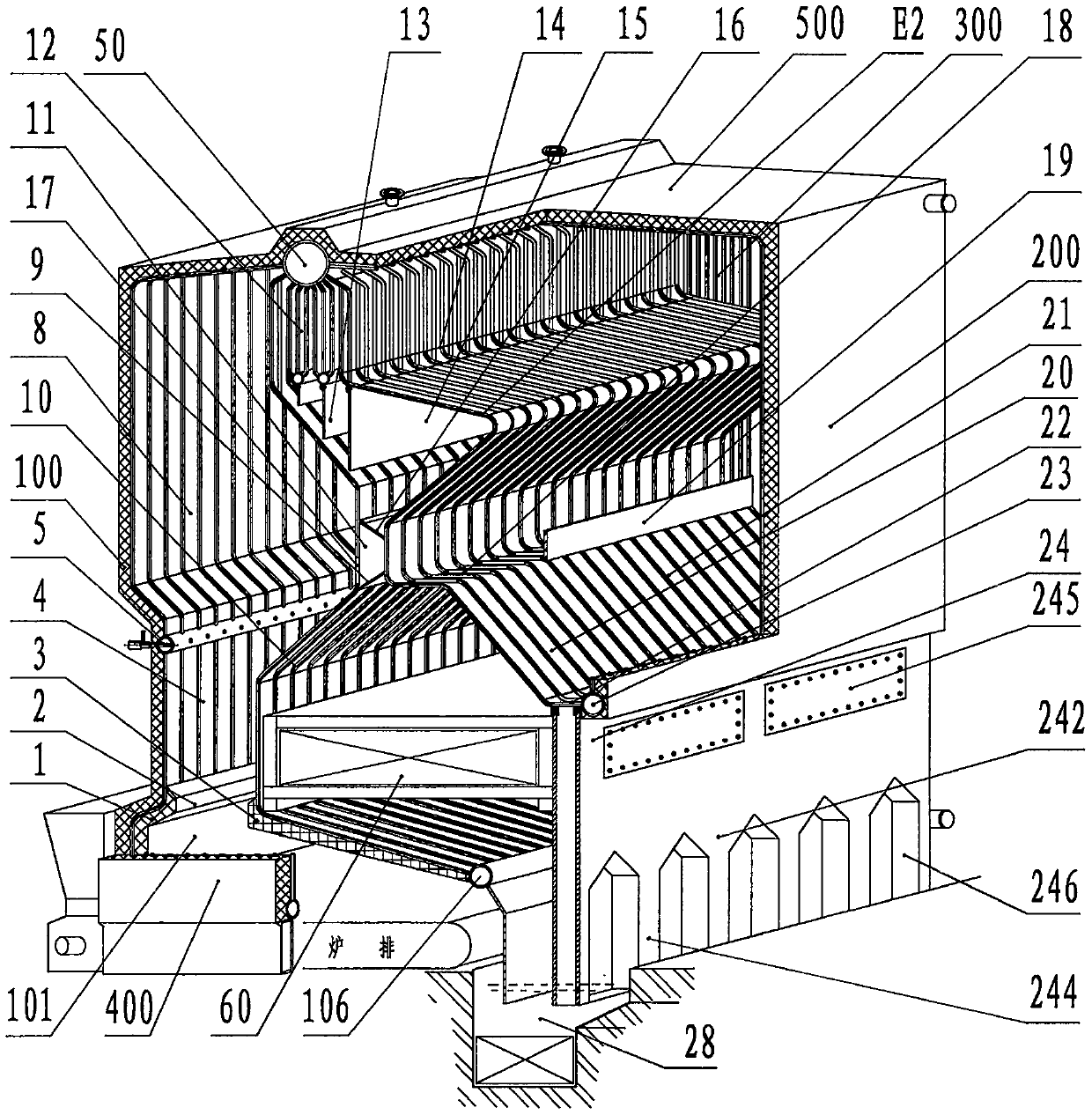
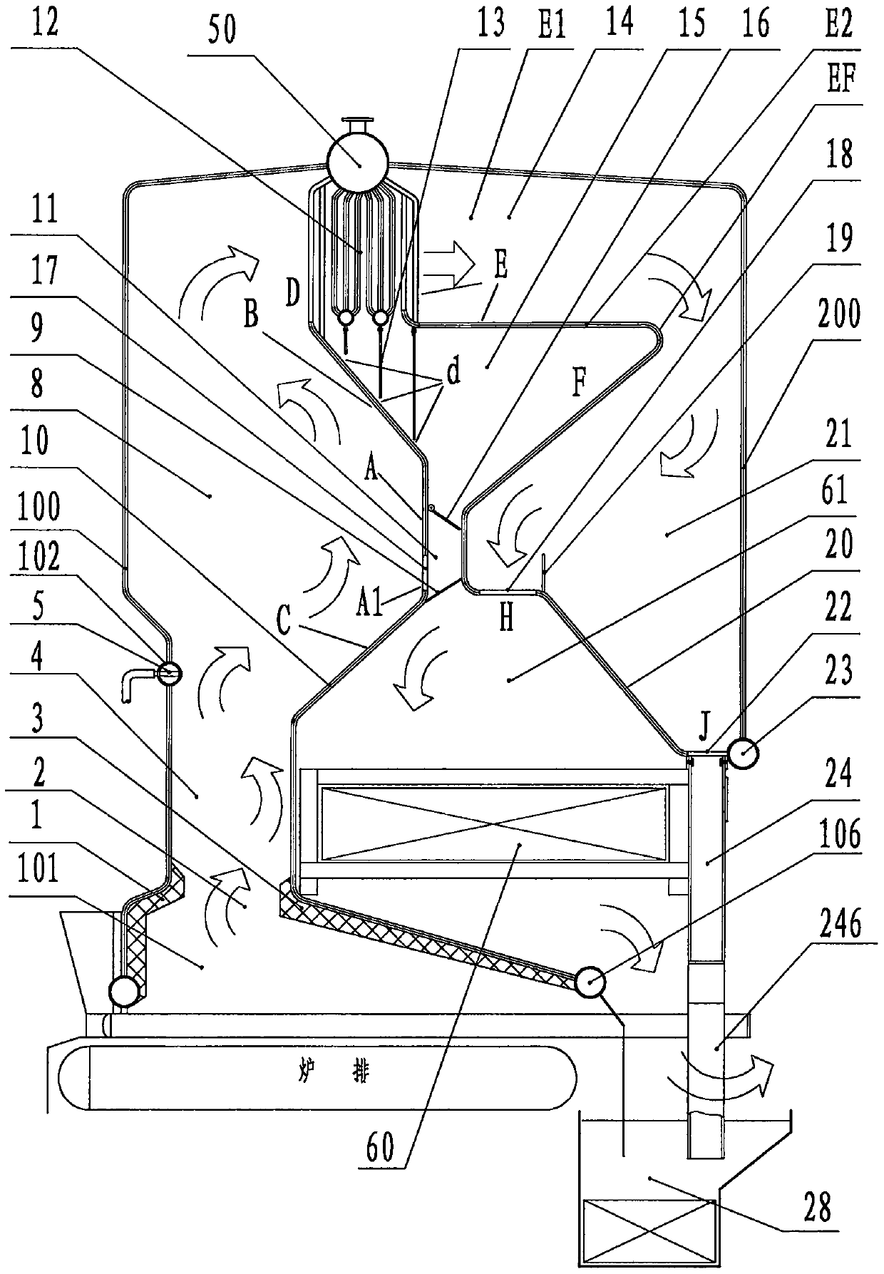
[0061] figure 1 and figure 2 A schematic cut-away perspective view of a boiler according to an embodiment of the invention and a corresponding schematic cross-sectional view are shown. This embodiment includes several aspects of the present invention, but those skilled in the art should understand from the following description that these aspects can be used in combination or alone. Details are given below.

[0062] see first figure 1 and figure 2 , The boiler according to this embodiment of the present invention has a front wall 100 , a rear wall 200 , a left wall 300 , a right wall 400 and a boiler top wall 500 . These walls define the interior space of the boiler. In the inner space, a front screen 10 and a rear screen 20 are provided. The front screen 10 is approximately perpendicular to the left wall and the right wall of the boiler and extends from the left wall to the right wall, and has a specific shape. The upper end of the front screen 10 is connected to the ...


PUM


Abstract

The invention provides a high-temperature denitration, fly ash re-ignition and in-furnace dust removal boiler. The high-temperature denitration, fly ash re-ignition and in-furnace dust removal boileris provided with a combustion chamber, a furnace and a long throat cavity connecting the combustion chamber with the furnace, and is further provided with a urea nozzle positioned adjacent to the junction of the long throat cavity and the furnace. The cross section of the long throat cavity is narrowed down relative to the combustion chamber and the furnace and the long throat cavity has a heightof 1-4 meters. In addition, the furnace is limited by a front wall, a left wall and a right wall of the boiler and a front screen in a specific shape, the front screen is approximately perpendicular to the left wall and the right wall and extends from the left wall to the right wall, the upper end of the front screen is connected to a boiler drum in the top wall of the boiler, and the lower end ofthe front screen is connected to a lower header of the front screen; and the part, limiting the furnace, of the front screen forms a concave surface facing the inner recess part of the front wall, and thus a travel path of flue gas is extended. In addition, the boiler includes a horizontal flue which communicates with the top of the furnace, the boiler is provided with a trough type separator located in the horizontal flue, a flue-dust retainer is arranged below the trough type separator, and the flue-dust retainer can selectively communicate with the furnace, so that collected flue dust is fed into the furnace for re-ignition.

Description

technical field [0001] The invention relates to a boiler, in particular to a high-temperature denitrification boiler with fly ash reburning and dust removal in the furnace. Background technique [0002] Nitrogen oxides (NOx) are one of the harmful substances emitted by boilers with smoke, and the control of NOx emissions is one of the most important measures to protect the atmospheric environment at present. For the control of NOx, the following methods are usually adopted. One is to reduce the combustion temperature by means of rich fuel and oxygen deficiency during combustion to reduce the amount of NOx produced by thermal nitrogen; the other is to perform non-catalytic reduction treatment on flue gas containing NOx to form Non-toxic nitrogen and water; third, catalytic treatment of low-temperature flue gas (at 350°C). [0003] From the perspective of application economy, convenience, and practicality, it is the best choice to control the amount of NOx generated during co...

Claims


Application Information

Patent Timeline
Patent Type & Authority Applications(China)
IPC IPC(8): F23B80/00F23J15/00F23J15/02F23M5/08F23J11/00
CPCF23B80/00F23J15/003F23J15/006F23J15/02F23J15/022F23M5/08F23J11/00F23J2215/10F23J2219/10F23J2217/20
Inventor 马成果
Owner 马成果
Why Eureka
Try Eureka