

Laser processing device
A laser processing and laser technology, applied in horticulture, botanical equipment and methods, plant cultivation, etc., can solve the problems of substrate deflection, processing position and focus shift, processing quality deterioration, etc., and achieve the effect of reducing deflection
Inactive Publication Date: 2015-09-16
V TECH CO LTD
View PDF5 Cites 0 Cited by
- Summary
- Abstract
- Description
- Claims
- Application Information
AI Technical Summary
Problems solved by technology
[0008] However, when the substrate is heated, it is expected that the substrate will be warped due to thermal expansion, and the processing position and focus will be shifted, resulting in deterioration of processing quality.
In addition, when the amount of deflection increases, it is likely that the surface of the substrate will come into contact with a part of the laser processing device to cause damage.
Method used
View moreImage
Smart ImageViewing Examples

Examples
Embodiment approach
[0064] 2. Variation
Embodiment approach )
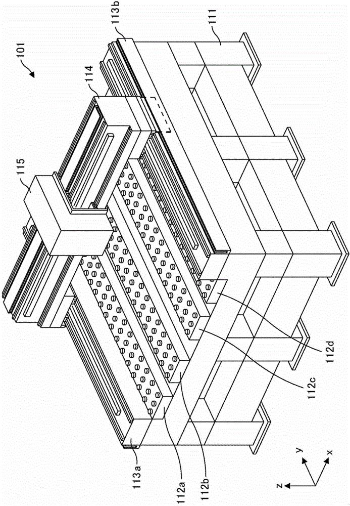
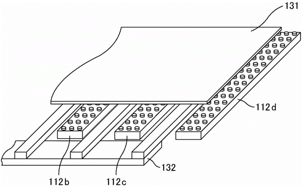
[0066] (Example of configuration of laser processing equipment)
Login to View More PUM
 Abstract
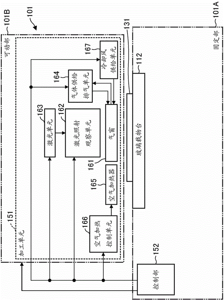
PURPOSE: A laser processing apparatus is provided to efficiently heat the periphery of a portion in which a chemical vapor deposition (CVD) process is performed, and to reduce the deformation of a target which will be processed. CONSTITUTION: A laser processing apparatus includes a cooling air feeding unit (167) and a laser unit (163) irradiating a laser beam to a portion which will be processed. The cooling air feeding unit jets material gas and hot air to the periphery of the portion on a target to be processed. The cooling air feeding unit jets the cooling air to the periphery from the outside a position from which the material gas and the hot air are jetted. An exhaust outlet for sucking the material gas, the hot air, and the cooling air is installed between the position from which the material gas and the hot air are jetted and a position from which the cooling air is jetted. [Reference numerals] (101A) Fixing unit; (101B) Operating unit; (112) Glass loading board; (151) Processing unit; (152) Control unit; (161) Gas window; (162) Laser irradiation monitoring unit; (163) Laser unit; (164) Gas supply exhaust unit; (165) Air heater; (166) Air heater control unit; (167) Cooling air feeding unit
Description
technical field [0001] The present invention relates to a laser processing device, in particular to a laser processing device for performing laser CVD (Chemical Vapor Deposition) processing. Background technique [0002] Currently, laser processing devices that use laser CVD (Chemical Vapor Deposition) to correct wiring defects on substrates used in display panels such as LCD (Liquid Crystal Display) panels and organic EL (Electro-Luminescence) panels are widespread. [0003] In a laser processing device using the laser CVD method, a raw material gas is supplied to the vicinity of the portion where the wiring on the substrate to be processed is corrected, and laser light is irradiated to the corrected portion on the substrate, and the raw material activated by the energy of the laser The gas acts as a film and accumulates in the corrected portion, thereby correcting the wiring on the substrate. However, when the raw material gas is supplied to the surface of the substrate, ...
Claims
Login to View More Application Information
Patent Timeline
 Patent Type & Authority Patents(China)
IPC IPC(8): C23C16/48
CPCA01G9/246A01G9/247A01G9/26A01G18/60
Inventor 中塚敬一
Owner V TECH CO LTD