Textile machine with movably fixed suction element

A suction element and textile machine technology, applied in spinning machines, textiles, papermaking, drafting equipment, etc., can solve the problems of difficult maintenance and difficulty in getting close to each suction element, etc.

Inactive Publication Date: 2013-09-11
MASCHINENFABRIK RIETER AG
View PDF9 Cites 1 Cited by
  • Summary
  • Abstract
  • Description
  • Claims
  • Application Information

AI Technical Summary

Problems solved by technology

[0004] A disadvantage of the known drafting device is that it is generally difficult to access the individual suction elements, making maintenance particularly difficult

Method used


Image

  • Textile machine with movably fixed suction element
  • Textile machine with movably fixed suction element
  • Textile machine with movably fixed suction element

Examples


Embodiment Construction

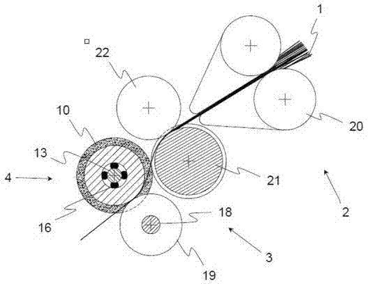
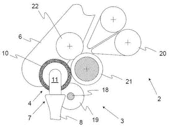
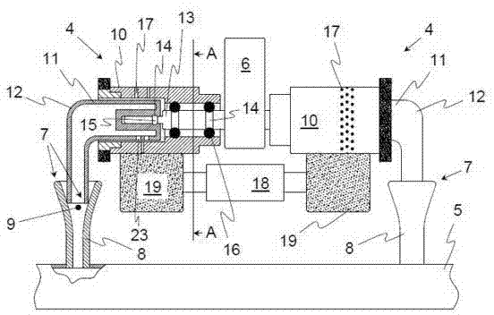
[0030] from Figures 1 to 4 The essence of the present invention can be learned from the summary in, wherein Figures 1 to 4 is a sectional view of a possible embodiment of a textile machine according to the invention, for example a ring spinning machine.

[0031] In general, a textile machine comprises a plurality of spinning stations arranged in a row, wherein a corresponding drafting device is arranged in each spinning station, by means of which a bundle of fine threads of the fiber composite material 1 introduced is processed. A stretching treatment followed by a compression treatment. Finally, the fiber composite material 1 that has undergone the above-mentioned processing steps enters a downstream spinning unit, where it is spun into yarns.

[0032] In this example, the drafting device comprises a drafting zone 2, wherein the drafting zone 2 comprises a pair of molding rolls 20 and a pair of trailing rolls. In this case, the end roll pair can have a centrally driven l...


PUM


Abstract

The invention relates to a textile machine. The textile machine has a drafting arrangement for drawing a fiber package (1), where the drafting arrangement has a delay zone (2) and a compression zone (3) that downstreams a delay zone (2) in the transport direction of the fiber package. The compression zone (3) has a suction element (4) for passing the fiber package for drawing the fiber package compressed in the delay zone. The suction element is fastened at a movably mounted support arm (6) and is moved into a maintenance position relative to a suction line (5) by the support arm. The suction element is connected with the suction line (5) in the maintenance position.

Description

technical field [0001] The invention relates to a textile machine comprising at least one drafting device for drafting a fiber composite material, wherein said drafting device comprises a drafting zone and a The direction of transport is placed in the compression zone downstream of the draft zone, wherein the compression zone has a suction element through which the fiber composite material must pass for compression in the draft zone The fiber composite material subjected to the drawing process, and wherein the suction element is connected in an operating position to a suction duct of the textile machine. Background technique [0002] For a corresponding drafting device of a universal textile machine (e.g. a ring spinning frame), the purpose is to card the fiber composite material introduced into the textile machine before it is introduced into the spinning unit of the machine itself . Here, the fiber composite is stretched and then compressed in the so-called compression...

Claims


Application Information

Patent Timeline
IPC IPC(8): D01H5/72
CPCD01H5/72
Inventor W·施特拉泽G·斯塔莱克
Owner MASCHINENFABRIK RIETER AG
Why Eureka
Try Eureka