Device and method for improving rate of mechanical penetration of directional deflecting section

A technology of deflection and commutator, which is applied in drilling equipment and methods, drilling equipment, earthwork drilling, etc. Arbitrary wellbore build-up rate requirements and the effect of improving economic benefits

Active Publication Date: 2013-09-11
SOUTHWEST PETROLEUM UNIV
View PDF5 Cites 8 Cited by
  • Summary
  • Abstract
  • Description
  • Claims
  • Application Information

AI Technical Summary

Problems solved by technology

[0004] The purpose of the present invention is to solve the problems of low drilling speed caused by the inability to effectively transmit the drilling pressure to the drill bit during the operation of the conventional directional build-up section, improve the overall drilling efficiency of the directional build-up section and further reduce the operating cost

Method used


Image

  • Device and method for improving rate of mechanical penetration of directional deflecting section
  • Device and method for improving rate of mechanical penetration of directional deflecting section
  • Device and method for improving rate of mechanical penetration of directional deflecting section

Examples


Embodiment Construction

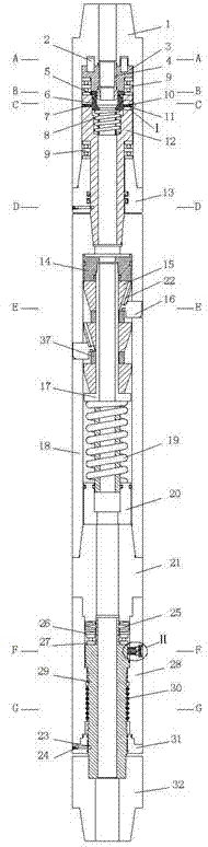
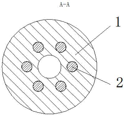
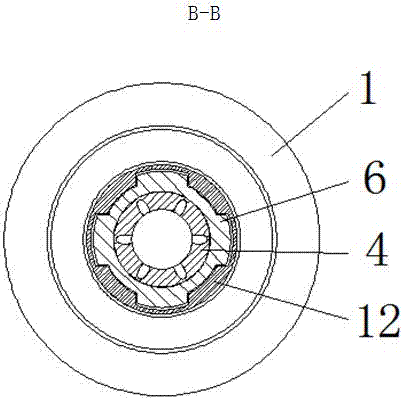
[0019] Depend on figure 1 As shown, the directional deflection and speed-up device involved in the present invention is composed of a torque adjustment nipple, a card arm nipple and a torsion elimination nipple; the torque adjustment nipple includes a torsion nipple housing (1), a cylindrical pin (2), an upload Moving part (3), lower transmission part (12), torque lock part (6), ball seat (4), two-way thrust ball bearing (9), screw pin (5), bayonet pin (11), bayonet hole Plug (10), bayonet spring (7), upper return spring (8), installation joint (13) and installation hole plug (23); cylindrical pin (2) and upper transmission part (3) are installed by interference fit, The remaining exposed section is inserted into the mounting hole of the torque nipple housing (1) corresponding to the cylindrical pin (2); the upper transmission part (3) and the lower transmission part (12) are internal spline structures, and the torque locking part (6) is an external Spline structure and under...


PUM


Abstract

The invention relates to a directional deflecting acceleration device and a using method thereof. The directional deflecting acceleration device comprises a torque regulating short section, a clamping arm short section and a torque eliminating short section. An upper transmission piece and a lower transmission piece of the torque regulating short section achieve synchronous connection and disconnection through a torque locking piece. The directional deflecting acceleration device is installed above a drill collar in a dynamic drill assembly. The pitching pressure-out is adopted to start the torque regulating short joint, regulate the torque locking piece and cut the torque transmitting from a rotary table to a drill bit. Meanwhile, a bi-directional thrust ball bearing combination continues to keep the drill pressure being transmitted to the drill bit. Pumping pressure is increased, the clamping arm short joint extends outwards out of a clamping arm to clamp the well wall, the torque eliminating short joint is matched to enable the clamping arm short joint and the drill assembly below the clamping arm short joint to relatively fix the well wall, and well inclination azimuth is kept unchangeable. The device is compact in structure, convenient to operate, and capable of thoroughly solving the problem that the rate of mechanical penetration of a directional deflecting section is low.

Description

technical field [0001] The invention relates to a directional deflection speed-increasing device capable of increasing the ROP of a directional deflection build-up section and an application method thereof. The device can effectively ensure the transmission of drilling pressure to the drill bit, cut off the transmission of the rotary table torque to the drill bit, and realize efficient and rapid drilling in the directional deflection section. Background technique [0002] When routinely implementing deflection building operations in the directional section, a special curved dynamic drilling tool is lowered, and the sliding drilling method is used to complete the adjustment of the well deflection azimuth and deflection building. In order to ensure the success of deflection, when using curved power drilling tools, the power of the turntable will be stopped, and the power drilling tools will be used to drive the drill bit to rotate. At this time, due to the stoppage of the tur...

Claims


Application Information

Patent Timeline
Patent Type & Authority Applications(China)
IPC IPC(8): E21B7/08
Inventor 祝效华敬俊
Owner SOUTHWEST PETROLEUM UNIV
Why Eureka
Try Eureka