
Coal mine automatic explosion-proof device with two-way triggering

A two-way triggering, coal mine technology, applied in safety devices, mining equipment, earth-moving drilling, etc., can solve the problems of increasing equipment cost and installation workload, unsafe device backwards, and inability to install devices, etc. The effect of fire extinguishing efficiency, convenient operation, and convenient production and assembly

Inactive Publication Date: 2015-08-05
SHANDONG LIYE MINE EXPLOSION PROOF EQUIP
View PDF5 Cites 3 Cited by
  • Summary
  • Abstract
  • Description
  • Claims
  • Application Information

AI Technical Summary

Problems solved by technology

The existing problems are: the explosion-proof can only be triggered in one direction; when the direction of explosion flame spread is uncertain, it has to be installed in pairs in two directions, which increases the equipment cost and installation workload; and, because the explosion-proof device must be installed in two groups, The required lateral area is large, and when the underground roadway is narrow and the installation equipment is complex and changeable, it will interfere with the device and cannot be installed
Firstly, it is not safe to place the device upside down, and secondly, it is serious to fill the powder from the incision, which is easy to cause environmental pollution and personal injury

Method used


Image

  • Coal mine automatic explosion-proof device with two-way triggering
  • Coal mine automatic explosion-proof device with two-way triggering
  • Coal mine automatic explosion-proof device with two-way triggering

Examples


Embodiment Construction

[0027] The present invention will be further described below in conjunction with drawings and embodiments.

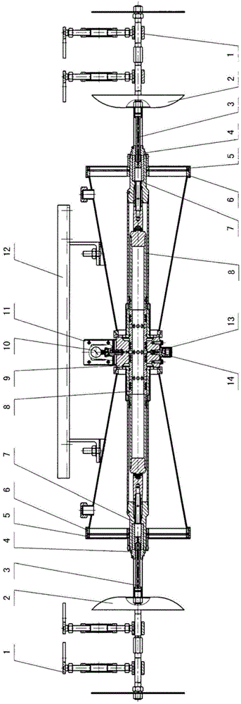
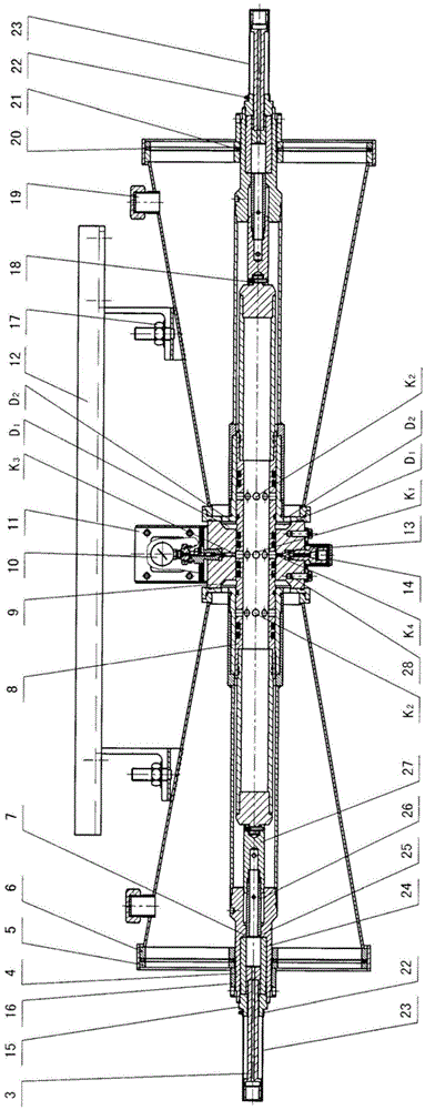
[0028] exist figure 1 The overall structure of the coal mine underground automatic flameproof device with two-way triggering of the present invention is shown in . The device is composed of a receiving rod hanging device 1, a shock wave receiving device 2, and a main body; the main body is composed of an action trigger assembly 7, an air jet pipe assembly 8, an intermediate sleeve assembly 9, an outer cover assembly 6, and a compacting screen assembly 5 , pressure gauge assembly 10, pressure gauge protective cover 11, valve needle 13, inflatable cover assembly 14, main body hanging device 12, etc. Among them, the receiving rod hanging device 1, the shock wave receiving device 2, the action triggering assembly 7, the outer cover assembly 6, and the pressing screen assembly 5 are two sets of left and right and arranged symmetrically with the axial vertical center line of...


PUM


Abstract

A mine under-shaft automatic explosive-suspension device triggered in two directions comprises receiving rod hanging devices, impact wave receiving devices, motion triggering components, transferring rod assemblies, outer-layer sleeve assemblies, air spraying pipe assemblies, middle sleeve assemblies, an outer cover assembly, a pressing sieve assembly, a pressure gauge component and pressure gauge protective cover, a valve needle and inflation cover assembly and a main body hanging device, the rest of the parts except the first two parts form the main body part, the number of each of the first seven parts is two, and the first seven parts are in bilateral symmetry regarding the axial vertical central line of the main body part as the center. The air spraying pipe assemblies are assembled inside axial center holes of the middle sleeve assemblies, are in sliding fit, are located in the center of the main body part, and are in bilateral symmetry regarding the axial vertical central line of the main body part as the center. The motion triggering components adopt safety gaskets. The mine under-shaft automatic explosive-suspension device triggered in the two directions is installed in an mine under-shaft tunnel with gas and coal duct explosion dangers, automatically suppressing an explosion in a bi-direction-triggered and spraying mode when the explosion occurs, and prevents the explosion from expanding and causing a secondary explosion, one set of the automatic explosive-suspension device replaces an original front set and an original reverse set, the cost of equipment is reduced, and installation and coal dust filling are convenient.

Description

technical field [0001] The invention relates to an automatic underground explosion-proof device for coal mine safety equipment, in particular to an automatic underground explosion-proof device for a coal mine that can be triggered bidirectionally to automatically isolate gas and coal dust explosions and prevent secondary explosions caused by explosion spread. Background technique [0002] China's "Utility Model Patent Bulletin" discloses a patent titled: "Automatic Explosion-proof and Explosion-Suppression Device for Mine", its application number: CN201020660338.7, application date: 2010.12.15, and publication number: CN201953397U. The device was trial-manufactured by Shandong Liye Mine Flameproof Equipment Co., Ltd. in 2010 and applied for a patent. The purpose of this patent is to trial-produce a purely mechanical explosion-proof device for isolating gas and coal dust explosions in coal mines; Form an explosion isolation area in a medium and large area for a long time, su...

Claims


Application Information

Patent Timeline
Patent Type & Authority Patents(China)
IPC IPC(8): E21F5/10
Inventor 于传利刘士金刘端来白倩尤里·果儿洛夫杨士行张琳琳
Owner SHANDONG LIYE MINE EXPLOSION PROOF EQUIP
Learn More