Engine inlet fuel temperature regulating system

A temperature regulation and engine technology, applied in the direction of engine components, machine/engine, turbine/propellant fuel delivery system, etc., can solve the problems of consuming the effective power of the aircraft engine, destroying the integrity of the aircraft shape, reducing the performance of the aircraft, etc., to avoid fuel consumption Icing Risk, Advancement of Physics Integration, Effects of Improving Aircraft Efficiency

Active Publication Date: 2013-09-11
XIAN AIRCRAFT DESIGN INST OF AVIATION IND OF CHINA
View PDF6 Cites 5 Cited by
  • Summary
  • Abstract
  • Description
  • Claims
  • Application Information

AI Technical Summary

Problems solved by technology

[0002] Existing aircraft use ram bleed air to dissipate heat from the aircraft's on-board systems. This method requires openings on the outer surface of the aircraft, which destroys the integrity of the aircraft's shape
At the same time, the ram bleed air cooling consumes the effective power of the aircraft engine and reduces the performance of the aircraft
In order to overcome the above-mentioned shortcomings, it is occasionally used to dissipate heat for other systems by connecting the engine oil supply pipeline in series with the radiator, but only if the radiator has a small power and a small number of radiators
With the development of aircraft electromechanical systems, it is required to be able to cool the radiator heat sources of multiple systems at the same time. System heat dissipation is likely to cause the fuel temperature to exceed the engine inlet temperature, causing engine failure

Method used


Image

  • Engine inlet fuel temperature regulating system
  • Engine inlet fuel temperature regulating system
  • Engine inlet fuel temperature regulating system

Examples


Embodiment Construction

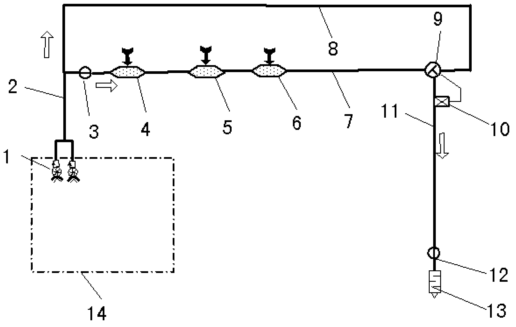
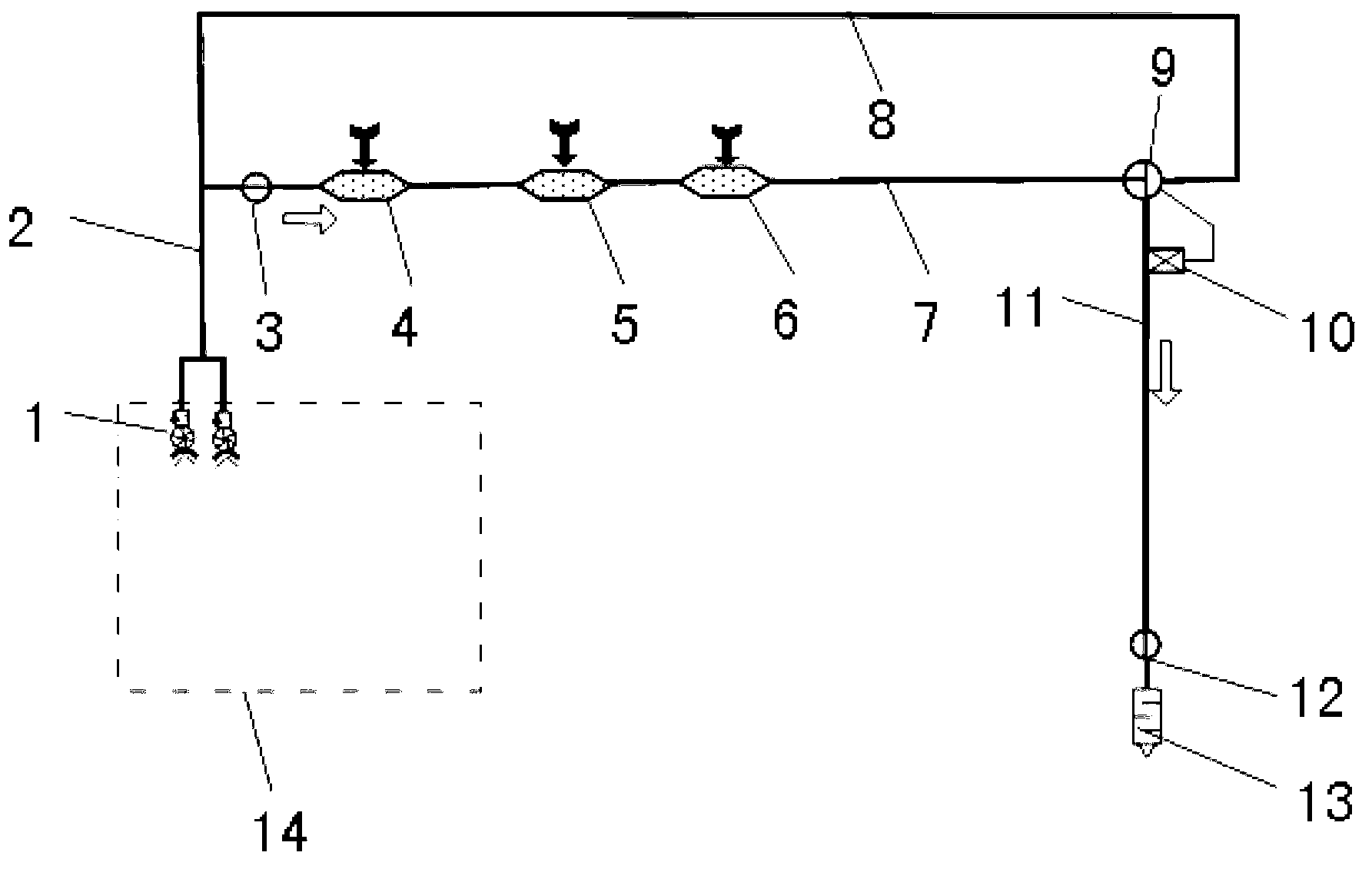
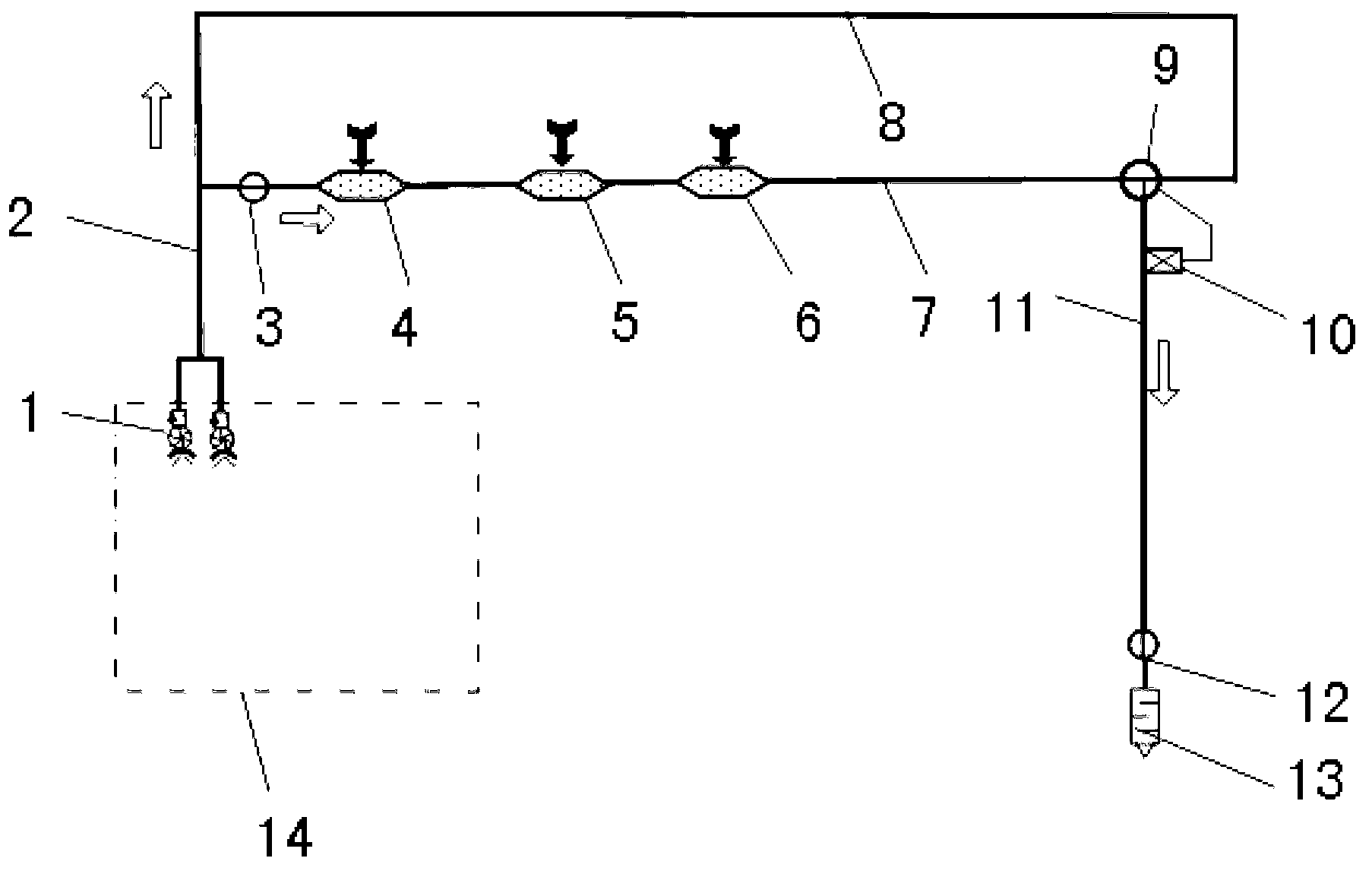
[0013] Below in conjunction with accompanying drawing the present invention is described in further detail, please refer to Figure 1 to Figure 4 .

[0014] Such as figure 1 As shown, a kind of engine inlet fuel temperature regulating system of the present invention, the outlet of two mutual backup oil supply pumps 1 located in the fuel tank 14 communicates with the engine oil supply pipeline 2 and is divided into two paths: heat dissipation path 7 and direct The oil supply circuit 8, the heat dissipation circuit 8 is provided with a cut-off valve 3, and after connecting the environmental control radiator 4, the hydraulic radiator 5 and the inert radiator 6, it merges with the direct oil supply circuit 8 through the three-position solenoid valve 9, and merges A temperature sensor 10 for providing a three-position solenoid valve 9 valve position control signal is installed on the pipeline 11 at the rear, and a fire protection cut-off valve 12 is installed before the entrance o...


PUM


Abstract

The invention belongs to the technical field of aviation fuel, and in particular relates to an engine inlet fuel temperature regulating system. According to the system, in a form of connecting a plurality of stages of radiators in series stage by stage on an engine oil supply pipeline, sub-systems of an electromechanical system, such as a hydraulic system, an environmental control system and an inerting system, are cooled; a heat dissipation requirement is met; an oil supply pipeline leading to an engine is connected in parallel to an oil supply pipeline on which the radiators are located; two paths of fuel are intersected through a three-position electromagnetic valve at an engine inlet; the three-position electromagnetic valve is controlled to respectively convey cold fuel, hot fuel and cold-hot mixed fuel to the engine; the fuel is utilized for heat radiation to the greatest extent on the premise of meeting a fuel temperature requirement of the engine inlet. According to the system, a requirement on heat radiation of a plurality of systems through the fuel is met, the temperature of the fuel entering the engine inlet can be controlled through operation of the three-position electromagnetic valve, the heat radiation capacity of the fuel is utilized to the greatest extent, and the energy integration of an aircraft is realized.

Description

technical field [0001] The invention belongs to the technical field of aviation fuel, and in particular relates to a system for adjusting the fuel temperature at the inlet of an engine. Background technique [0002] Existing aircraft widely use ram bleed air to dissipate heat from the aircraft's on-board systems. This method requires openings on the outer surface of the aircraft, which destroys the integrity of the aircraft's shape. At the same time, the ram bleed air cooling consumes the effective power of the aircraft engine and reduces the performance of the aircraft. In order to overcome the above-mentioned shortcomings, it is occasionally seen that the engine oil supply pipeline is connected in series with radiators to dissipate heat for other systems, but this is only limited to small radiator power and a small number of radiators. With the development of aircraft electromechanical systems, it is required to be able to cool the radiator heat sources of multiple system...

Claims


Application Information

Patent Timeline
Patent Type & Authority Applications(China)
IPC IPC(8): F02C7/224F02M31/16
Inventor 韩琦刘苏彦刘小锋罗景锋
Owner XIAN AIRCRAFT DESIGN INST OF AVIATION IND OF CHINA
Why Eureka
Try Eureka