
Air suction type threaded pipe air pre-heater and threaded smoke pipe coal economizer combined device

A technology of air preheater and threaded smoke pipe, which is applied in the field of boilers, can solve the problems of easy condensation of flue gas, acid corrosion of air preheater, low heat exchange efficiency, etc., and achieve adjustable blast temperature, Improved service life and high heat exchange efficiency

Active Publication Date: 2013-09-11
陈懿修 +1
View PDF6 Cites 2 Cited by
  • Summary
  • Abstract
  • Description
  • Claims
  • Application Information

AI Technical Summary

Problems solved by technology

[0002] The flue gas of the conventional boiler air preheater goes through the tube side and the air goes through the shell side, and the flue gas goes through the tube side and is easy to condense in the tube, which will cause acid corrosion to the air preheater and affect its service life
The conventional air preheater is installed on the air outlet of the blower. The blower sucks in low-temperature cold air and then blows it into the air preheater. The air preheater exchanges hot air and then sends it into the boiler blast duct. The temperature of the hot air in the air duct is likely to cause burning damage to the reciprocating grate that does not require high-temperature blast
In addition, the heat exchange tubes of conventional air preheaters and economizers are all bare tubes, and their heat exchange efficiency is low, which is not conducive to preheating cold water or minimizing boiler exhaust gas temperature. If it is too low, it is easy to cause the flue gas condensation to form acid corrosion

Method used


Image

  • Air suction type threaded pipe air pre-heater and threaded smoke pipe coal economizer combined device

Examples


Embodiment Construction

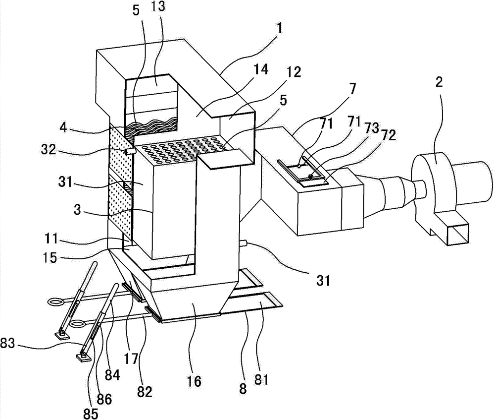
[0010] Such as figure 1 As shown, it includes a shell 1, a blower 2, an economizer 3 and an air preheater 4, and the economizer 3 and the air preheater 4 are installed on the flue gas inlet 12 side and the flue gas passage 11 of the shell 1 respectively. On the side of the flue gas outlet 13, the economizer 3 is composed of a closed water tank shell 33 with a water inlet 31 and a water outlet 32, and a plurality of threaded pipes 5 located inside the water tank shell 33 and penetrating the water tank shell 33 along the flue gas flow direction. The air preheater 4 is composed of a plurality of threaded pipes 5 arranged between the opposite side walls of the housing 1 and passing through the side walls of the housing 1 perpendicular to the flow direction of the flue gas. The air inlet 21 of the blower 2 passes through the air box 7 and the The threaded pipes 5 constituting the air preheater 4 are connected at the nozzles on one side of the housing 1 , and the side wall of the b...


PUM


Abstract

The invention relates to an air suction type threaded pipe air pre-heater and threaded smoke pipe coal economizer combined device which comprises a casing (1), an air blower (2), a coal economizer (3) and an air pre-heater (4). The coal economizer (3) is formed by an airtight water tank casing (33) and a plurality of threaded pipes (5) located in the water tank casing (33). The air pre-heater (4) is formed by a plurality of threaded pipes (5) penetrating the side wall of the casing (1). An air inlet (21) of the air blower (2) is connected with pipe orifices of the threaded pipes (5) which form the air pre-heater (4) through an air bellow (7), and adjustable air distribution ports (71) are arranged on the side wall of the air bellow (7). By using the air suction type threaded pipe air pre-heater and threaded smoke pipe coal economizer combined device, smoke gases are unlikely to dew, acid corrosion of the air pre-heater is avoided, the service life of the air pre-heater can be prolonged, the temperature of hot air blown into an air blowing flue of a boiler can be adjusted conveniently, burning loss of reciprocating grates with no high temperature air blowing requirements is avoided, the heat exchange efficiency is high, cold water pre-heating is benefited, and the boiler discharge smoke temperature can be reduced to be the lowest conveniently.

Description

technical field [0001] The invention relates to a boiler, in particular to a combination device of an air preheater and an economizer. Background technique [0002] Conventional boiler air preheater flue gas goes through the tube side and air goes through the shell side, and the flue gas goes through the tube side and is prone to condensation in the tube, which will cause acid corrosion to the air preheater and affect its service life. The conventional air preheater is installed on the air outlet of the blower. The blower sucks in low-temperature cold air and then blows it into the air preheater. The air preheater exchanges hot air and then sends it into the boiler blast duct. The temperature of the hot air in the air duct is likely to cause burning damage to the reciprocating grate that does not require high-temperature blast. In addition, the heat exchange tubes of conventional air preheaters and economizers are all bare tubes, and their heat exchange efficiency is low, w...

Claims


Application Information

Patent Timeline
Patent Type & Authority Applications(China)
IPC IPC(8): F22D1/38F24H9/00
Inventor 陈懿修鲍守明
Owner 陈懿修
Learn More