Optical mixing rod vibration structure for laser illumination speckle reduction

A laser lighting and light mixing rod technology, applied in the field of laser lighting, can solve problems such as energy loss, hindering application, lighting energy loss, etc., achieve efficient lighting shaping, eliminate speckle, and solve the problem between speckle elimination and energy efficiency. contradictory effect

Inactive Publication Date: 2013-09-11
BEIHANG UNIV
View PDF6 Cites 6 Cited by
  • Summary
  • Abstract
  • Description
  • Claims
  • Application Information

AI Technical Summary

Problems solved by technology

For laser projection applications, the approach of using scatterers leads to a loss of illumination energy, which hinders the application of this method in practical laser projection techniques
[0004] Another technical approach is the speckle elimination technology based on the rotating light mixing rod, which can suppress the speckle contrast while maintaining the energy of the original beam, but the laser spot suppressed by this method is circular, while the currently commonly used Both the projection chip and the projection picture are rectangular. In the actual lighting stage, the mismatch between the shape of the spot and the shape of the photo chip will cause energy loss. To match the two, an additional shaping lens group is required

Method used


Image

  • Optical mixing rod vibration structure for laser illumination speckle reduction
  • Optical mixing rod vibration structure for laser illumination speckle reduction
  • Optical mixing rod vibration structure for laser illumination speckle reduction

Examples


Embodiment Construction

[0024] The present invention will be further described in detail with reference to the accompanying drawings and embodiments.

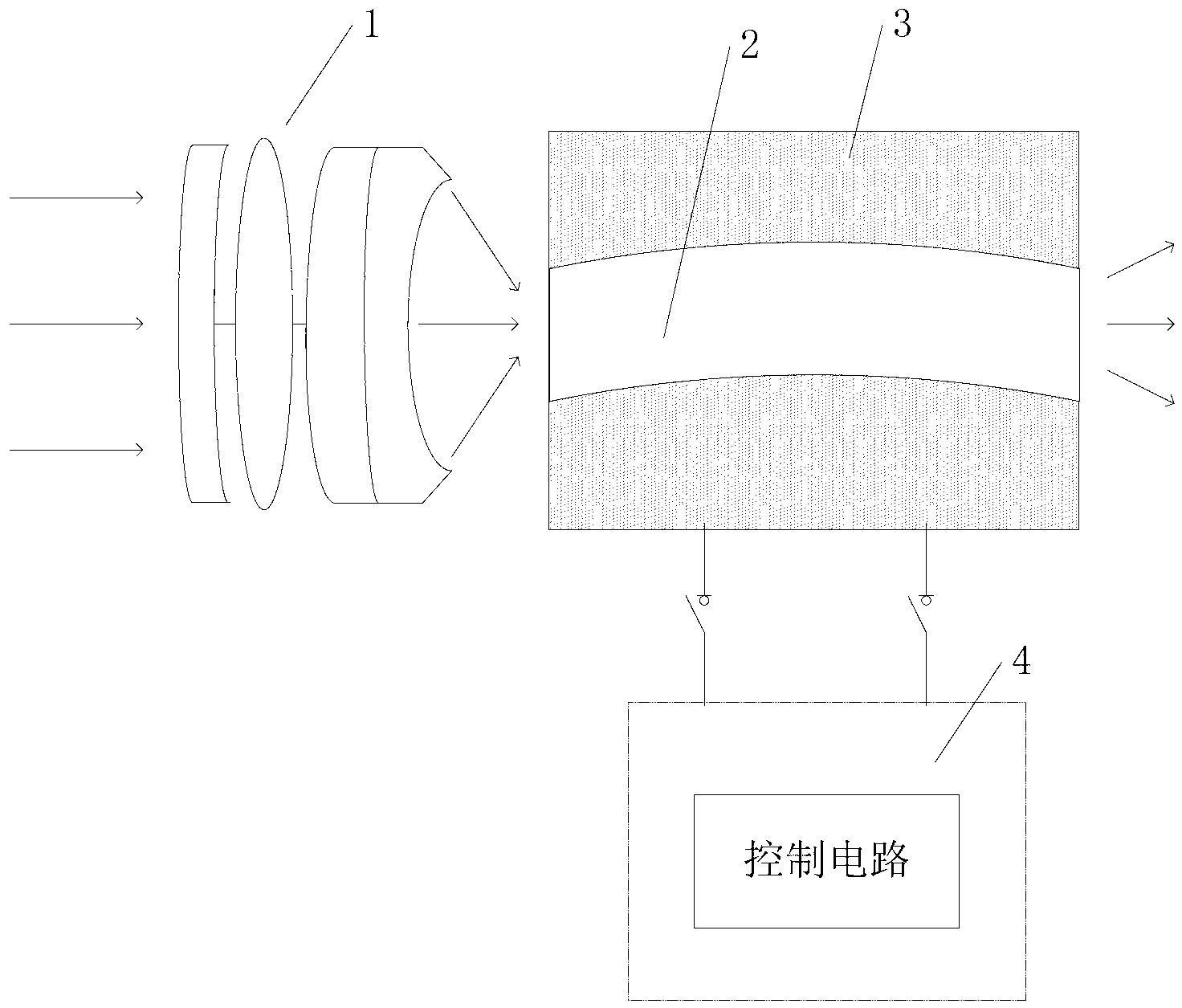
[0025] The invention is a light mixing rod vibration structure used for laser illumination speckle elimination, such as figure 1 As shown, it includes a coupling lens 1 , a light mixing rod 2 , a vibration mechanism 3 and a control circuit 4 .

[0026] The light source emits monochromatic laser light, the laser light enters the coupling lens 1 , the coupling lens 1 converges the laser light emitted by the light source, and outputs it to the incident surface of the light mixing rod 2 .

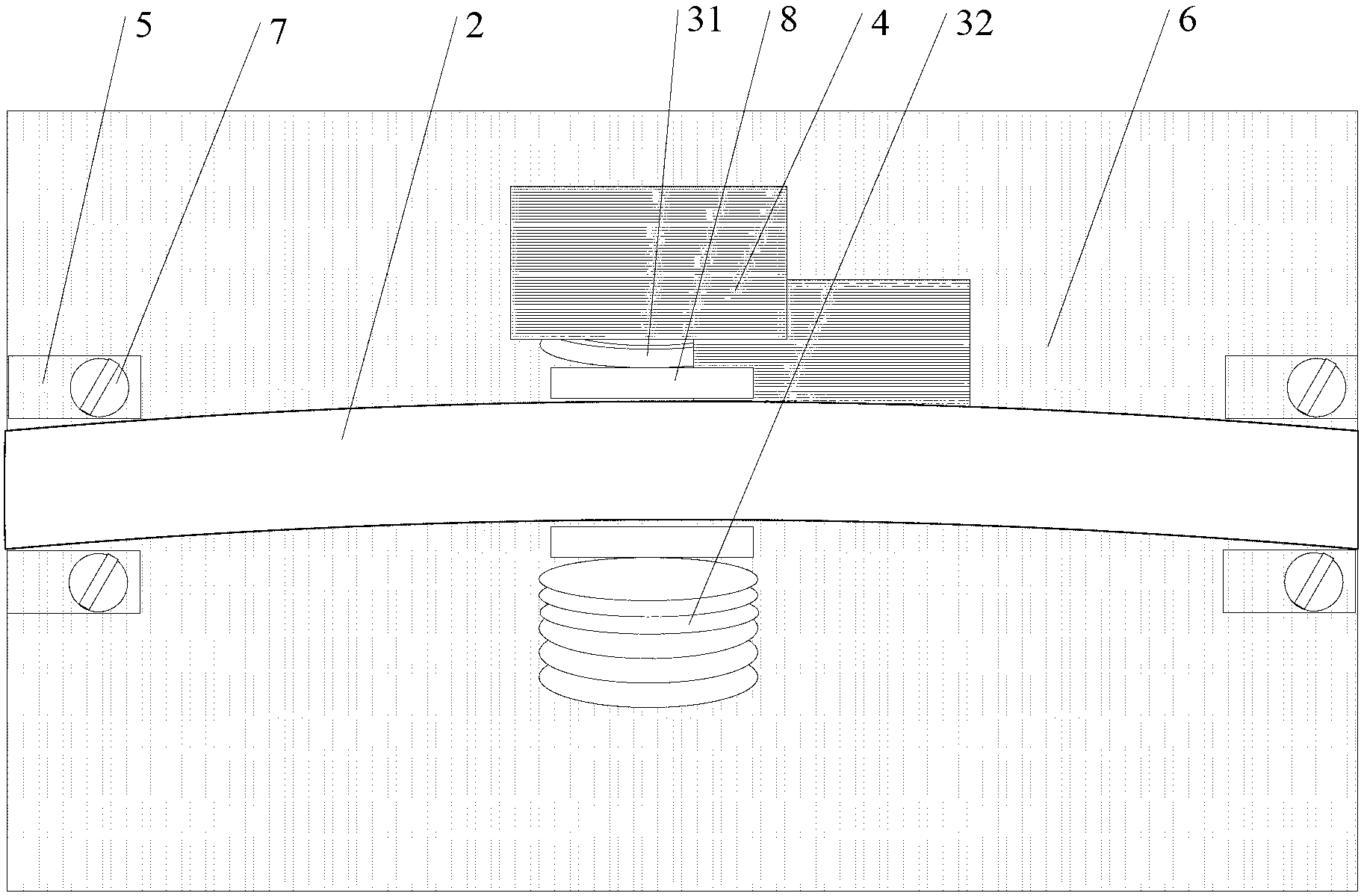
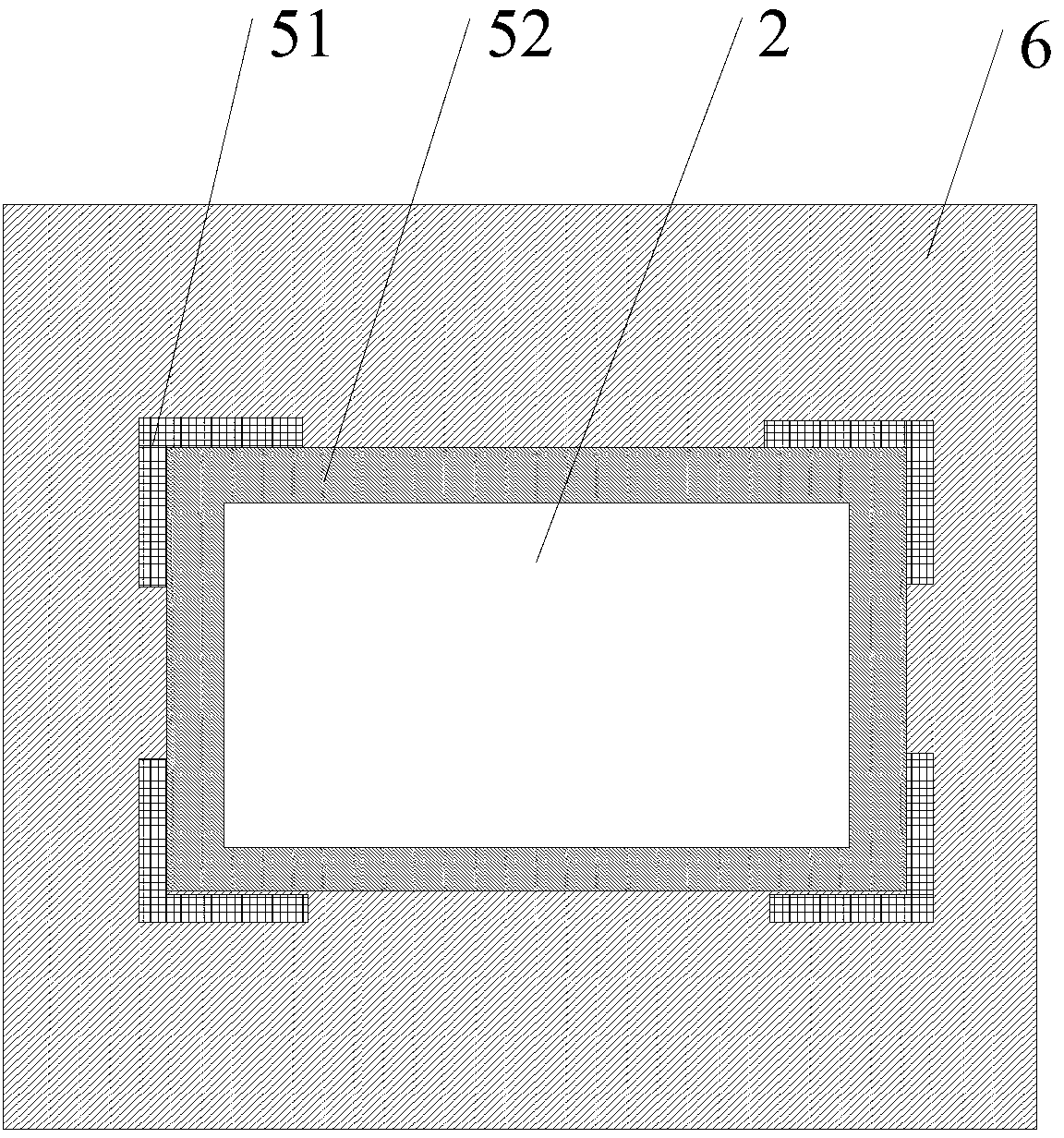
[0027] The light mixing rod 2 is located in the vibrating mechanism 3, and the vibrating mechanism 3 drives the light mixing rod 2 to vibrate with equal amplitude. In the non-vibrating state, the axis of the light mixing rod 2 coincides with the optical axis of the laser output from the coupling lens 1, and the laser beam passes through the light mixing rod 2 and is o...


PUM


Abstract

The invention provides an optical mixing rod vibration structure for laser illumination speckle reduction, and belongs to the technical field of laser illumination. The optical mixing rod vibration structure comprises a coupling lens, an optical mixing rod, a vibration mechanism and a control circuit; laser emitted by an optical source is gathered via the coupling lens, is outputted into an incident surface of the optical mixing rod and is outputted via an emergent surface of the optical mixing rod; the optical mixing rod is fixed into the vibration mechanism and vibrates vertically in a constant amplitude manner. The axis of the optical mixing rod is coincided with the optical axis of the laser outputted by the coupling lens when the optical mixing rod is in a non-vibration state. The control circuit controls the amplitude and the frequency of vibration of the vibration mechanism. The optical mixing rod vibration structure has the advantages that an extra shaping lens which is an optical device is omitted, efficient shaped illumination is implemented, and the size of a system is reduced; the energy efficiency and a polarization characteristic of the laser are maintained while speckles are reduced.; the shape of a speckle-free illumination spot is matched with that of a projection chip, and the energy utilization efficiency of illumination beams is improved.

Description

technical field [0001] The invention relates to a light mixing rod vibration structure used for laser lighting speckle elimination, and belongs to the technical field of laser lighting. Background technique [0002] Compared with traditional light sources, the display technology using laser as light source has the advantages of wide color gamut, high resolution, long life, high brightness, compact optical system, and high photoelectric conversion efficiency. It is often used in the field of projection lighting. But when the laser is irradiated on a rough surface (such as a projection screen), the scattered light will interfere with each other, forming a random light intensity distribution in the subsequent propagation space. This distribution of light intensity is observed by an intensity detector (such as the human eye) and is the so-called speckle phenomenon. Speckle seriously affects the projected image quality, which is one of the bottlenecks in laser lighting applicati...

Claims


Application Information

Patent Timeline
Patent Type & Authority Applications(China)
IPC IPC(8): G02B27/48
Inventor 孙鸣捷于康龙孟照魁张春熹
Owner BEIHANG UNIV
Why Eureka
Try Eureka