
LED backlight driving circuit, driving method of LED backlight driving circuit and liquid crystal display device
A technology of backlight drive circuit and LED light bar, which is applied in the direction of static indicators, instruments, etc., can solve the problems that the LED backlight drive circuit cannot be identified, and cannot provide short-circuit protection for LED light bars, etc.
- Summary
- Abstract
- Description
- Claims
- Application Information
AI Technical Summary
Problems solved by technology
Method used
Image

Examples
Embodiment 1
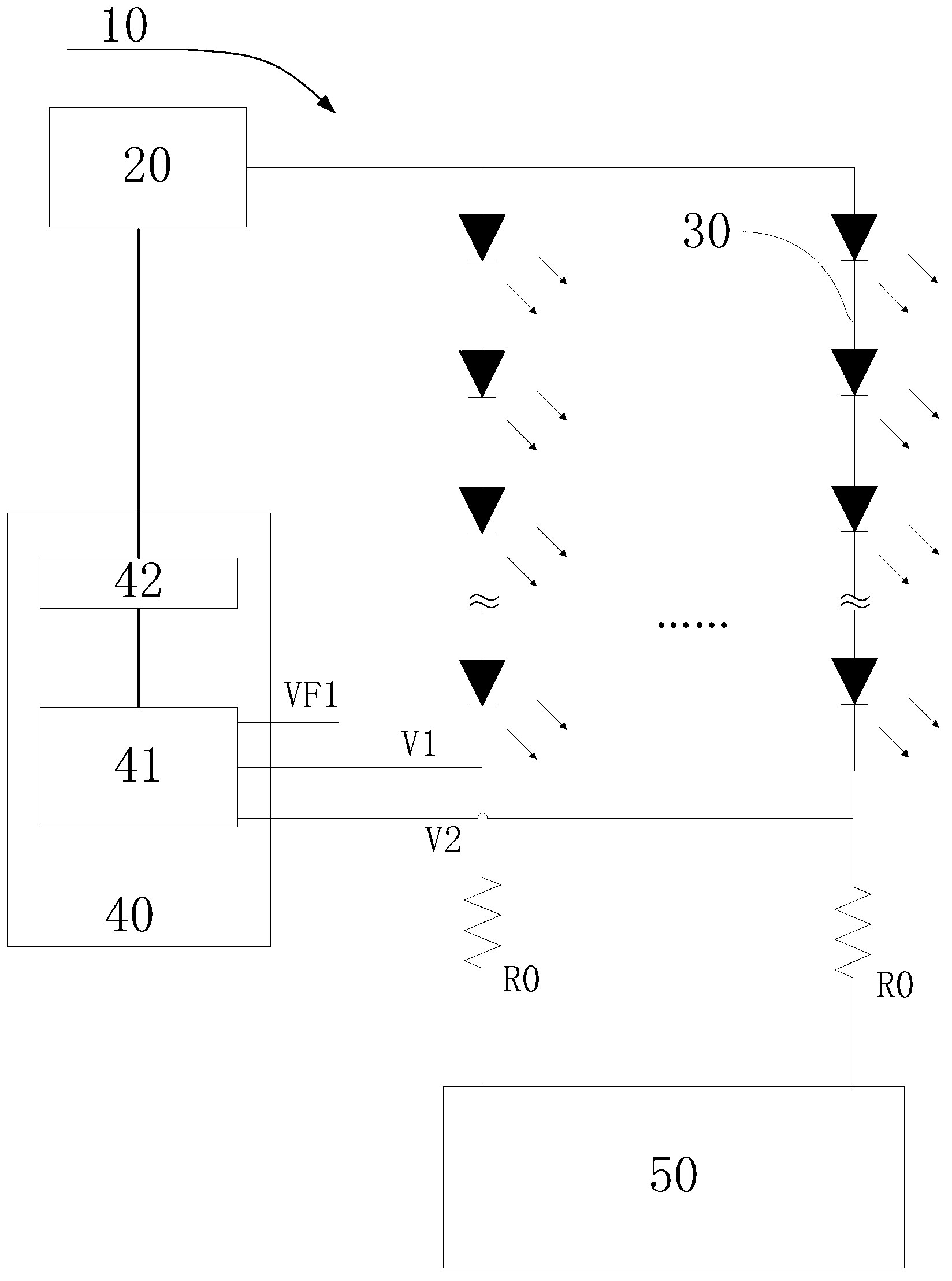
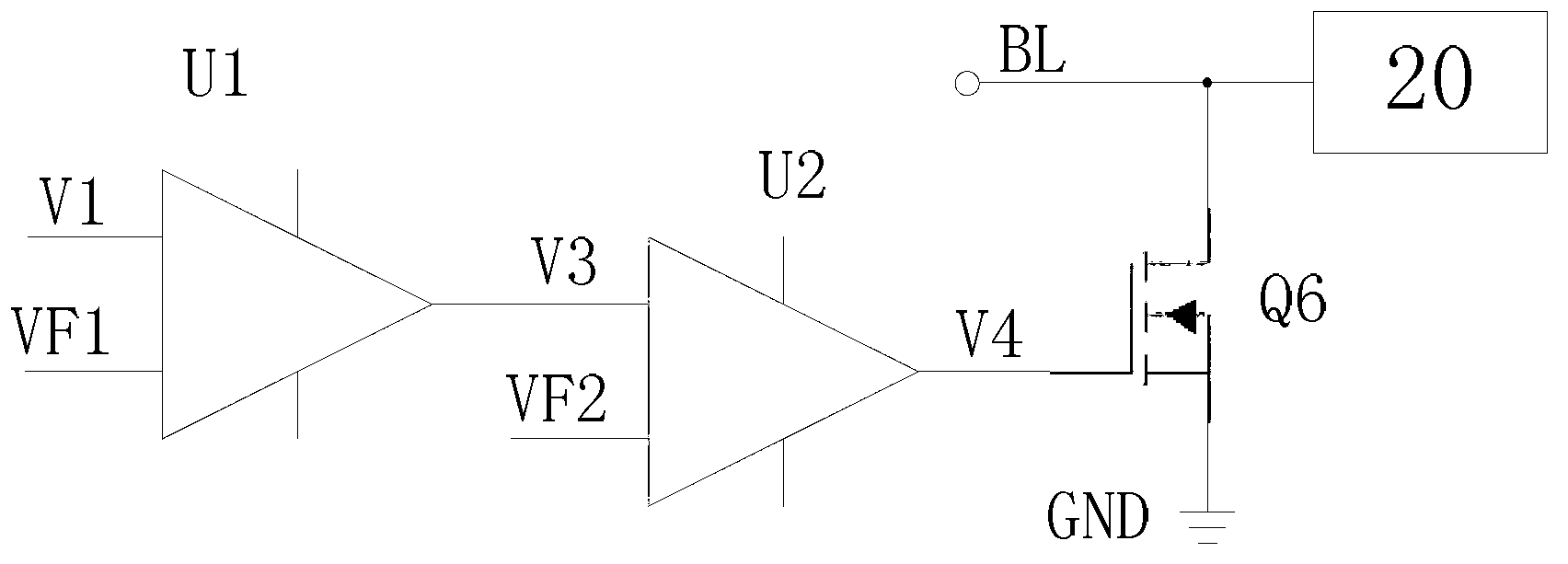
[0058] Such as figure 1 , 2 As shown, the comparison unit in this embodiment includes a subtractor U1, a first input terminal of the subtractor U1 is coupled to the feedback voltage V1; a second input terminal thereof is coupled to the first reference voltage VF1. The difference between the feedback voltage and the first reference voltage VF1 can be directly output through the subtractor U1, so that the subsequent drive unit only needs to judge whether the difference exceeds a preset deviation value, and if it exceeds, the drive power supply module is turned off.
[0059] The driving unit includes a comparator U2, the first input terminal of the comparator U2 is coupled to the output terminal of the subtractor U1; the second input terminal of the comparator U2 is coupled with a second reference voltage VF2;
[0060] The second reference voltage VF2 is equal to the preset deviation value, and when the output voltage of the subtractor U1 is greater than the second reference vol...
Embodiment 2
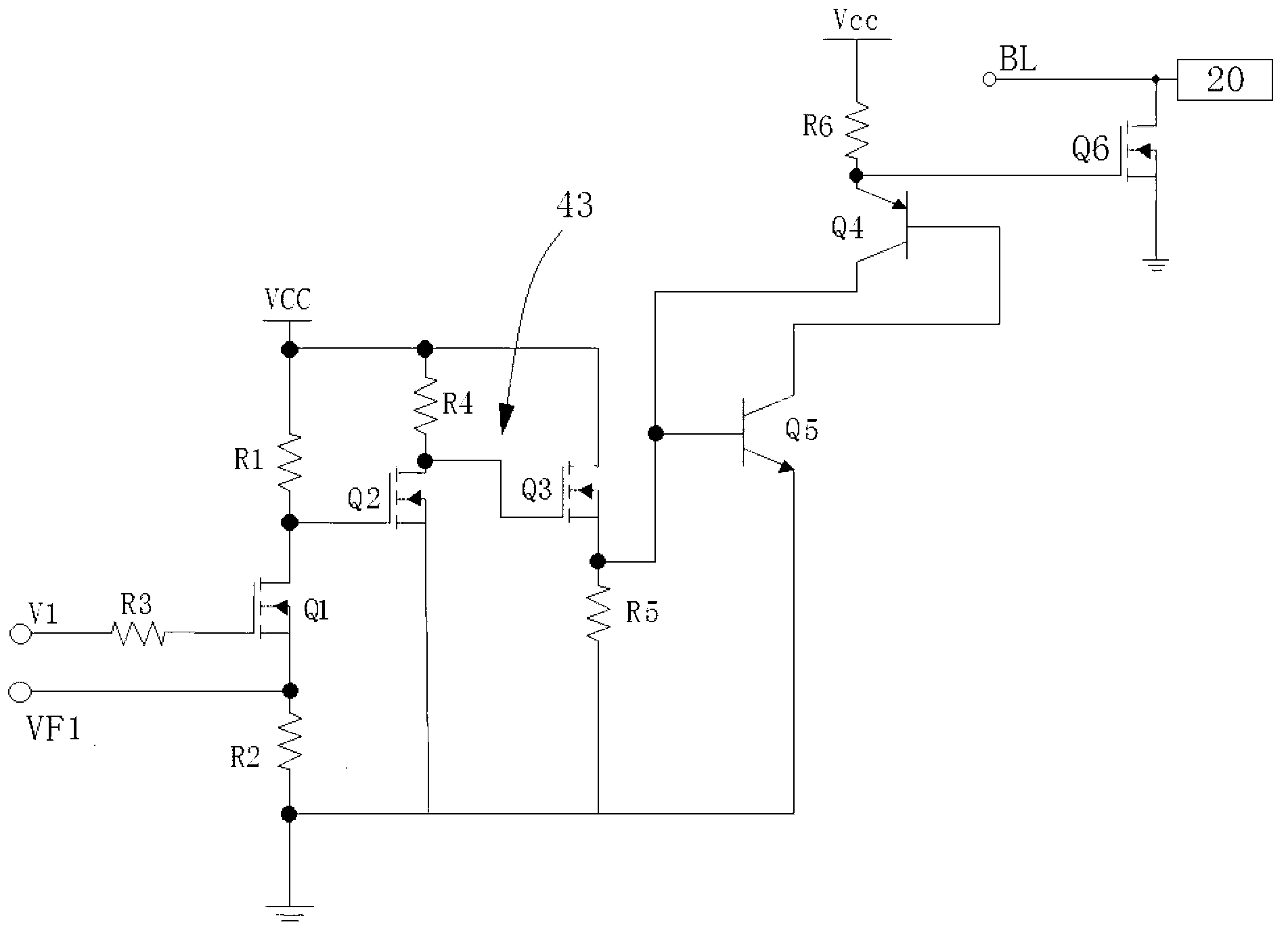
[0064] Such as figure 1 , 3 As shown, the comparison unit in this embodiment includes a first controllable switch Q1, a first resistor R1, a second resistor R2 and a third resistor R3; the source of the first controllable switch Q1 is coupled to A reference high-level signal VCC, the drain of which is coupled to the ground terminal of the LED backlight drive circuit through the second resistor R2; the feedback voltage V1 is coupled to the gate of the first controllable switch Q1 through the third resistor R3; the second A reference voltage VF1 is coupled to the drain of the first controllable switch Q1; the source of the first controllable switch Q1 is also coupled to an inverter 43, and the output terminal of the inverter 43 is coupled to the drive unit ;
[0065] The inverter 43 includes a second controllable switch Q2, a third controllable switch Q3, a fourth resistor R4, and a fifth resistor R5;
[0066] The source of the second controllable switch Q2 is coupled to the ...
Embodiment 3
[0077] Such as Figure 4 Shown, a kind of driving method of LED backlight driving circuit, described LED backlight driving circuit comprises LED light bar, drives the power supply module of LED light bar, and described driving method comprises steps:
[0078] A: Connect the voltage dividing resistor R0 in series at the output end of the LED light bar; preset the first reference voltage VF1 and the deviation value;
[0079] The first reference voltage VF1 is greater than or equal to the maximum voltage at both ends of the divider resistor R0 when the normal LED light bar is at maximum brightness;
[0080] B: The voltage at both ends of the voltage dividing resistor R0 is compared with the first reference voltage VF1 as the feedback voltage, and if the difference between the feedback voltage and the first reference voltage VF1 exceeds a preset deviation value, the power supply module is controlled to be turned off.
PUM
 Abstract
Description
Claims
Application Information