Switching arrangement in gas-insulated or vacuum-insulated switchgear assemblies

A power distribution device, vacuum insulation technology, applied in the direction of circuits, electric switches, electrical components, etc., can solve the problem of high complexity of maintenance and achieve a good cost-effective effect

Active Publication Date: 2013-09-11
HITACHI ENERGY SWITZERLAND AG
View PDF3 Cites 0 Cited by
  • Summary
  • Abstract
  • Description
  • Claims
  • Application Information

AI Technical Summary

Problems solved by technology

Maintenance complexity is correspondingly high

Method used


Image

  • Switching arrangement in gas-insulated or vacuum-insulated switchgear assemblies
  • Switching arrangement in gas-insulated or vacuum-insulated switchgear assemblies
  • Switching arrangement in gas-insulated or vacuum-insulated switchgear assemblies

Examples


Embodiment Construction

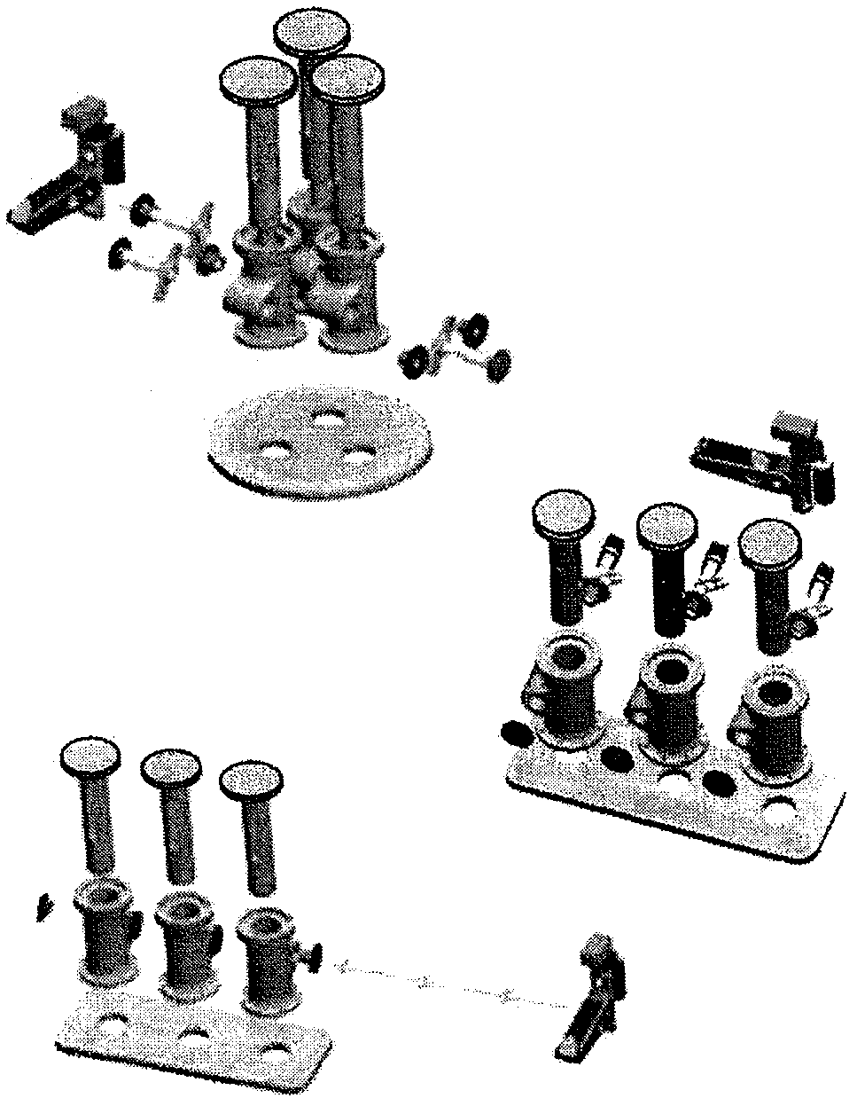
[0071] figure 1 A power distribution device built from standard modules is shown, which meets different requirements. Three such distribution units are in figure 1 shown in . Power distribution units built from standard modules are available in Figures 2 to 5 shown in detail.

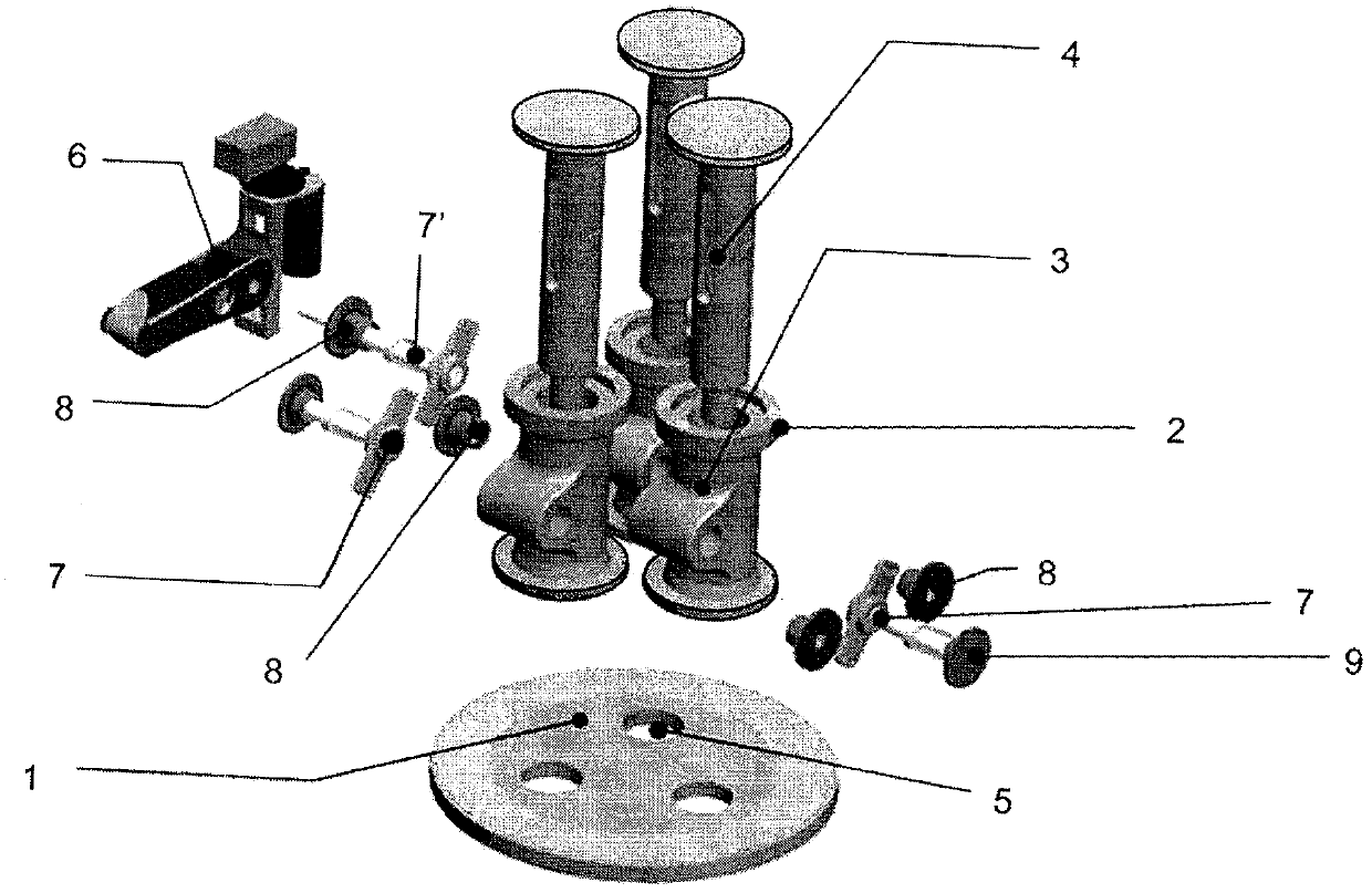
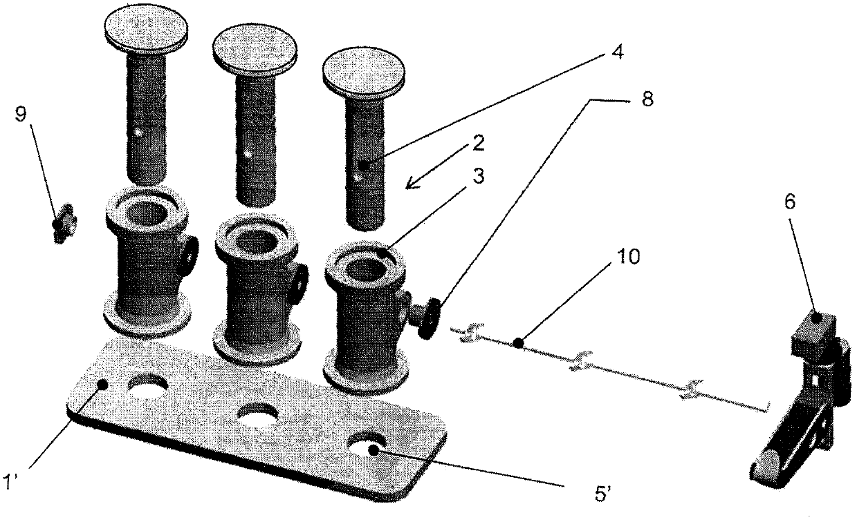
[0072] figure 2 A base carrier module 1 is shown for receiving a single-contact module 2 . The single-contact module 2 consists of a housing 3 and a moving contact carrier 4 . The base carrier module 1 has a circular hollow 5 whose midpoints form an equilateral triangle.

[0073] in addition, figure 2 A bistable electromechanical drive module 6 is shown, which can be connected to the single-contact module 2 via one actuator connection assembly 7' and two further connection assemblies 7. In addition, a dynamic sealing module 8 and a static sealing module 9 are arranged on the connecting components 7, 7'.

[0074] figure 2 A power distribution device is shown, comprising a drive module 6 , w...


PUM


Abstract

The invention relates to a switching arrangement for use in gas-insulated or vacuum-insulated switchgear assemblies, comprising a drive module (6) that closes or opens electrical contacts and a base carrier module (1, 1') on which individual contact modules (2) are arranged. In view of the aim to provide a compact electromechanical switching arrangement that can be scaled and configured unproblematically using as few components as possible such that said switching arrangement is suitable for a plurality of applications, the invention is characterized in that the individual contact modules (2) are identical in construction.

Description

technical field [0001] The invention relates to a switching device for use in gas-insulated or vacuum-insulated switchboards according to the general concept of claim 1 . Background technique [0002] A typical electromechanical switchgear operates the contact system of an electrical power switch, a circuit breaker, an earthing switch or a combined circuit breaking and earthing switch in the distribution instrumentation of the switchboard. It is used in particular in the medium and high pressure ranges. [0003] High demands are placed on such a power distribution device, especially in the aforementioned areas. It must be extremely reliable and demonstrate stability against vibrations and overloads. [0004] Power distribution units must operate stably over a wide temperature range and ensure safe automatic and manual operation. The operating mode or switching state must be reliably visualized and short reaction or response times must be provided during mechanical as well...

Claims


Application Information

Patent Timeline
Patent Type & Authority Applications(China)
IPC IPC(8): H01H33/60H01H33/02H01H33/42
CPCH01H33/42H01H33/6662H01H2033/024
Inventor 弗朗茨-约瑟夫·克贝尔格雷戈尔·斯特伦格尔洛塔尔·海涅曼塞巴斯蒂安·布赖施斯文·泽特比尔托马斯·布劳恩托马斯·施塔尔蒂莫西·维托托比亚斯·舍恩贝格沃尔夫冈·沃尔迪
Owner HITACHI ENERGY SWITZERLAND AG
Why Eureka
Try Eureka