
Photoelectric cabling-convenient distribution cabinet

A power distribution cabinet and photoelectric technology, which is applied in the direction of busbar/line layout, etc., can solve the problems of poor sealing of photoelectric separation, unfavorable and reasonable wiring, and narrow installation space, so as to achieve convenient and fast construction, reduce connection short circuit, and compact structure reasonable effect

Inactive Publication Date: 2013-09-11
STATE GRID CORP OF CHINA +3
View PDF5 Cites 0 Cited by
  • Summary
  • Abstract
  • Description
  • Claims
  • Application Information

AI Technical Summary

Problems solved by technology

The optical separation part of the optical fiber composite low-voltage cable is not well sealed, and the optical cable is folded back out of the cable hole, and the layout is not standardized; the cables entering and exiting the low-voltage cable branch cabinet are all up and down, which takes up a large horizontal space, and it is not convenient to install them in the vertical direction of the cable shaft. Reasonable use of space; and the construction and installation space in the cabinet is narrow, which is not conducive to reasonable wiring

Method used


Image

  • Photoelectric cabling-convenient distribution cabinet

Examples


Embodiment Construction

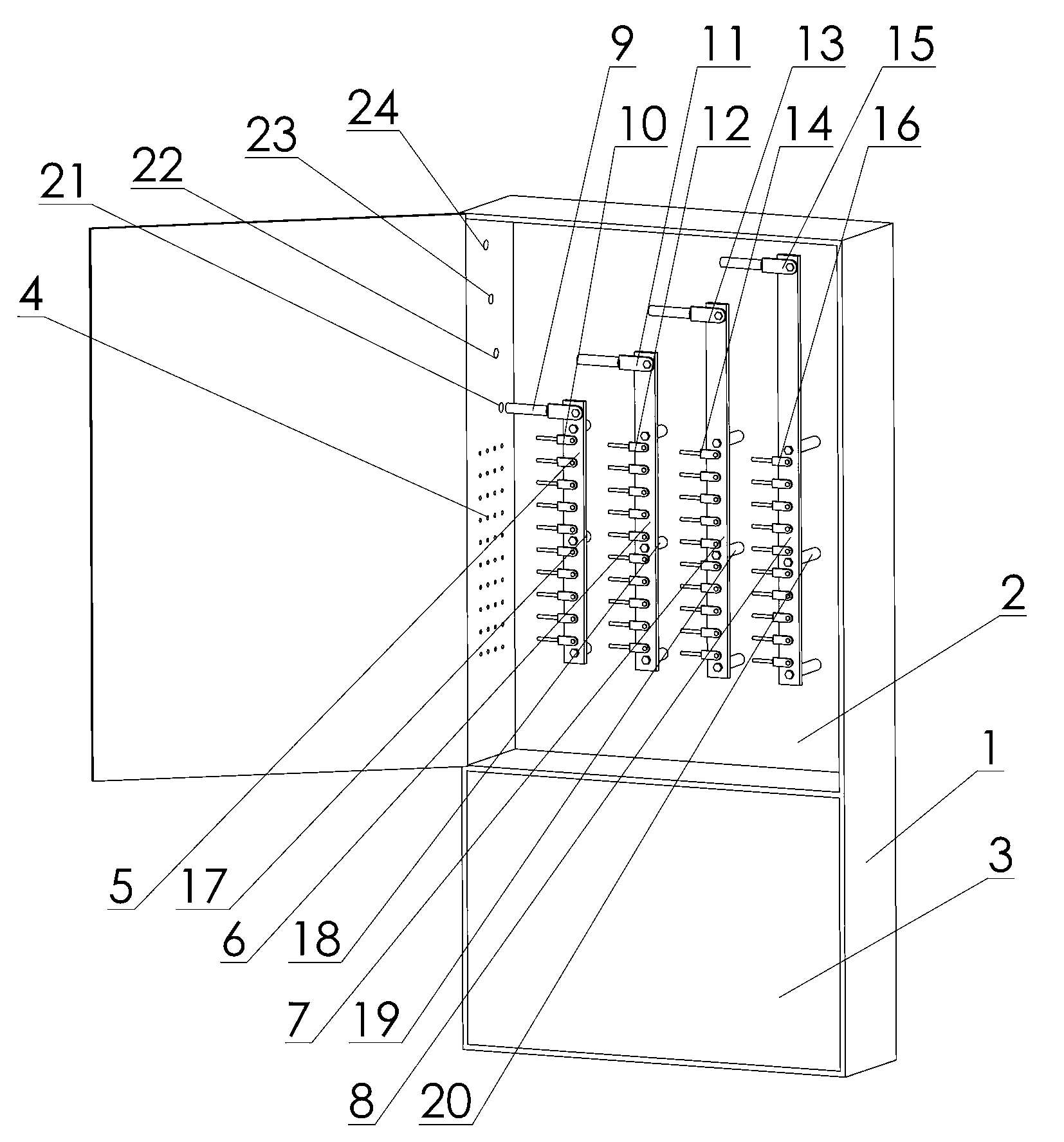
[0010] as attached figure 1 As shown, the present invention includes a cabinet body 1 and a power distribution unit 2 at the upper end of the cabinet body 1 and an optical unit 3 at the lower end. Type B pole busbar 6, detachable C pole busbar 7 and detachable zero busbar 8, the detachable A pole busbar 5, detachable B pole busbar 6, detachable C pole busbar The row 7 and the detachable zero busbar 8 are respectively installed on the first insulating fixed row 17, the second insulating fixed row 18, the third insulating fixed row 19 and the fourth insulating fixed row 20, and the first insulating fixed row 17 , The heights of the second insulating fixed row 18, the third insulating fixed row 19, and the fourth insulating fixed row 20 are stepped from left to right, and the detachable A-pole busbar 5 is provided with an A-pole incoming terminal 9 And more than one A-pole outgoing line terminal 10, the detachable B-pole busbar 6 is provided with a B-pole incoming line terminal ...


PUM


Abstract

The invention relates to a photoelectric cabling-convenient distribution cabinet comprising a cabinet body, a distribution unit and an optical unit, wherein the distribution unit and the optical unit are arranged at the upper and lower ends of the cabinet body respectively. The photoelectric cabling-convenient distribution cabinet is characterized in that a detachable A-electrode bus bar, a detachable B-electrode bus bar, a detachable C-electrode bus bar and a detachable zero bus bar are arranged in the distribution unit and are respectively installed to a first insulation fixing bar, a second insulation fixing bar, a third insulation fixing bar and a fourth insulation fixing bar, and height from the first to fourth insulation fixing bars is in step shape from left to right. Cable inlet and outlet is designed in left-right structure, the detachable four-electrode bus bars are installed and distributed according to practical cabling, cable inlet can be selected according to practical conditions, disorder of the cables is solved, accidents about cabling short circuit are reduced, cable inlet and outlet is neat and attractive in appearance, and arrangement of elements in the cabinet is optimized. Accordingly, the photoelectric cabling-convenient distribution cabinet is compact and reasonable in structure, attractive in appearance and convenient and quick to construct, and space of cable shafts of buildings is saved to the greatest extent.

Description

[0001] technical field [0002] The invention relates to a photoelectric power distribution cabinet which is convenient for internal wiring. Background technique [0003] Optical fiber composite low-voltage cable (OPLC) integrates optical fiber and copper wire for power transmission and distribution. It is another emerging optical fiber composite cable after optical fiber composite overhead ground wire (OPGW) and optical fiber composite overhead phase wire (OPPC). The optical separation part of the optical fiber composite low-voltage cable is not well sealed, and the optical cable is folded back out of the cable hole, and the layout is not standardized; the cables entering and exiting the low-voltage cable branch cabinet are all up and down, which takes up a large horizontal space, and it is not convenient to install them in the vertical direction of the cable shaft. Reasonable use of space; and the construction and installation space in the cabinet is narrow, which is not c...

Claims


Application Information

Patent Timeline
Patent Type & Authority Applications(China)
IPC IPC(8): H02B1/20
Inventor 郭成涛白云飞孙钊石磊杨彦龙钟成陈嘉麟王建军焦彦杰宋红红
Owner STATE GRID CORP OF CHINA
Learn More