Check patentability & draft patents in minutes with Patsnap Eureka AI!

Amplifier

A technology of amplifiers and amplifying components, which is applied in the direction of high-frequency amplifiers, amplification control, amplifier input/output impedance improvement, etc., and can solve problems such as uneven impedance

Inactive Publication Date: 2013-09-11
FUJITSU LTD
View PDF9 Cites 2 Cited by
  • Summary
  • Abstract
  • Description
  • Claims
  • Application Information

AI Technical Summary

Problems solved by technology

[0005] However, in the conventional technology described above, since the impedance matching circuit has an impedance frequency characteristic, when a broadband signal is input, the impedance within the frequency band of the signal becomes non-uniform

Method used


Image

  • Amplifier
  • Amplifier
  • Amplifier

Examples


Embodiment Construction

[0038] Preferred embodiments of the present invention will be described with reference to the accompanying drawings.

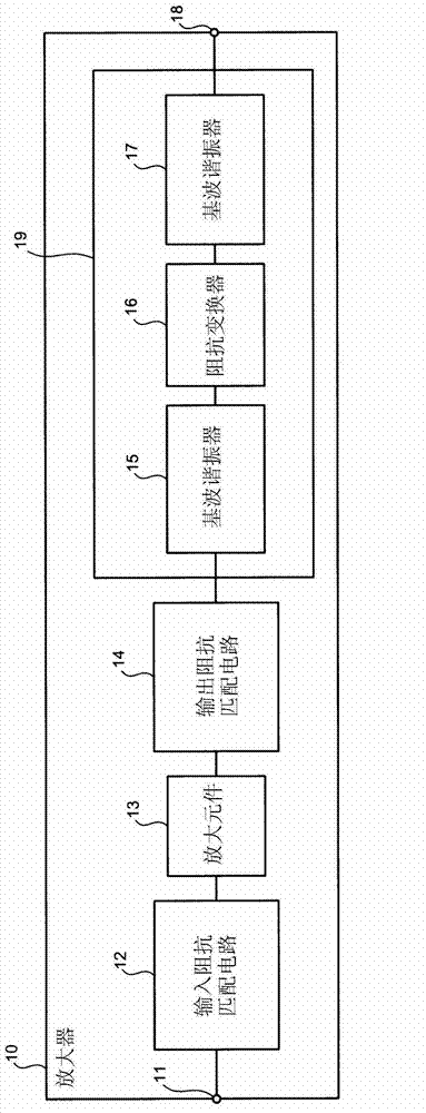
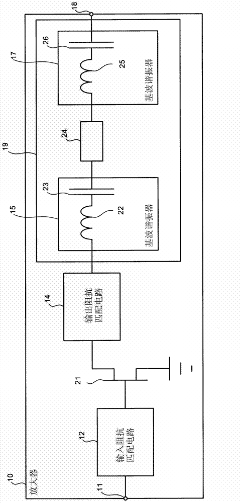
[0039] figure 1 One example of the configuration of the amplifier according to the first embodiment is shown. Such as figure 1 As shown, the amplifier 10 according to the first embodiment has an input terminal 11 , an input impedance matching circuit 12 , an amplifying element 13 , an output impedance matching circuit 14 , a compensation circuit 19 and an output terminal 18 . The amplifier 10 is, for example, an amplifier that amplifies a high-frequency signal. The signal (electrical signal) amplified by the amplifier 10 is input to the input terminal 11 . The signal input to the input terminal 11 is output to the input impedance matching circuit 12 .

[0040] The input impedance matching circuit 12 outputs the signal output from the input terminal 11 to the amplifying element 13 , and performs impedance matching of the input terminal 11 and the amplifying...


PUM


Abstract

An amplifier includes an amplifying element that amplifies an input signal; an output terminal that outputs the signal amplified by the amplifying element; a matching circuit disposed in series between the amplifying element and the output terminal, and performing impedance matching; an impedance converter disposed in series between the amplifying element and the matching circuit or between the matching circuit and the output terminal; and a first resonator and a second resonator connected at the ends of the impedance converter.

Description

technical field [0001] Embodiments discussed herein relate to amplifiers. Background technique [0002] A radio communication device of a mobile communication system, for example, uses an amplifier to amplify a high-frequency signal (see, for example, Japanese Patent Publication No. 2010-268248, International Publication No. 2009 / 131138, Japanese Translation Publication No. Patent Publication No.2009-213090). In this amplifier, for example, impedance matching circuits are provided on the input side and output side of the amplifying element. [0003] The impedance matching circuit on the input side of the amplifier converts, for example, the characteristic impedance (for example, 50 [Ω]) of the input terminal of the amplifier into the complex conjugate of the input impedance of the amplifying element. The impedance matching circuit on the output side of the amplifier converts, for example, the characteristic impedance (for example, 50 [Ω]) of the output terminal of the ampl...

Claims


Application Information

Patent Timeline
Patent Type & Authority Applications(China)
IPC IPC(8): H03F1/56
CPCH03F1/56H03F3/189H03G1/00
Inventor 马庭透木村重一
Owner FUJITSU LTD
Features
  • R&D
  • Intellectual Property
  • Life Sciences
  • Materials
  • Tech Scout
  • Unparalleled Data Quality
  • Higher Quality Content
  • 60% Fewer Hallucinations
Learn More