Light field image sensor, method and applications

A sensor and pixel technology, applied in the field of light field sensing and light field image detection, can solve the problems that are not suitable for the use of imager arrays

Active Publication Date: 2013-09-11
CORNELL UNIVERSITY
View PDF2 Cites 23 Cited by
  • Summary
  • Abstract
  • Description
  • Claims
  • Application Information

AI Technical Summary

Problems solved by technology

It has been reported that this method can be used to measure a single angle, but is not suitable for use on imager arrays

Method used


Image

  • Light field image sensor, method and applications
  • Light field image sensor, method and applications
  • Light field image sensor, method and applications

Examples


example 1

[0175] Example 1: Refocusing and finding range using light field data

[0176] One way to constrain the above problem is to assume that s is the result of visual information at a certain depth of focus, and find a best estimate of how the image should look if the detected rays originate only from that plane. s can now describe a plane of scale X×Y, so that s has X×Y=N 2 yuan. Although the matrix A is actually smaller than the matrix r, so A is not a square matrix, but it is "wider", and its "width" is greater than its "height", so the problem is now over-defined. By using the pseudo inverse transform (A T A) -1 A T , this transformation is usually used in overconstrained systems to obtain the best fit to s given r. If the fit is reasonably good (as you can get by choosing the right focal plane), then this approach can achieve a good approximation of the actual object scene. More specifically, if the approximation of s is

[0177] s'=p inv (A)r

[0178] where p inv (A...


PUM


Abstract

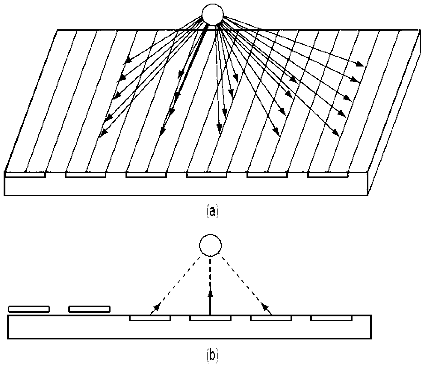
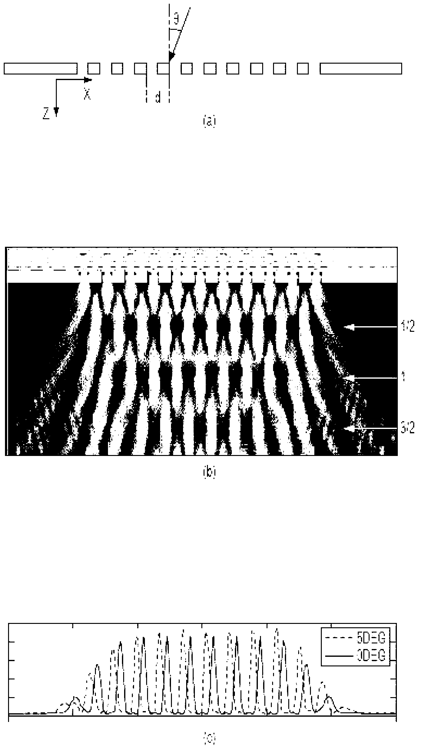
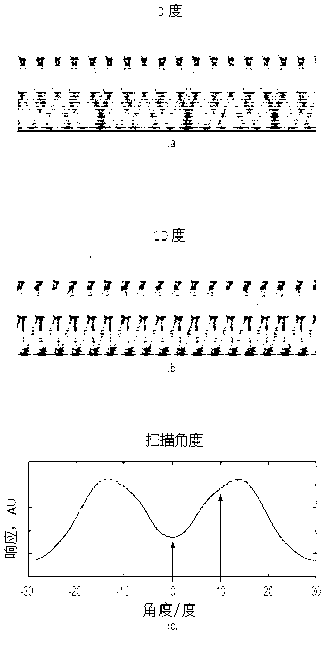
An angle-sensitive pixel (ASP) device that uses the Talbot effect to detect the local intensity and incident angle of light includes a phase grating disposed above a photodiode assembly or a phase grating disposed above an analyzer grating that is disposed above a photodiode assembly. When illuminated by a plane wave, the upper grating generates a self-image at a selected Talbot depth. Several such structures, tuned to different incident angles, are sufficient to extract local incident angle and intensity. Arrays of such structures are sufficient to localize light sources in three dimensions without any additional optics.

Description

[0001] relevant application data [0002] This application claims priority to U.S. Provisional Patent Application No. 13 / 055,566, filed April 6, 2011, and is related to application PCT / US09 / 51660, filed July 24, 2009, and the The subject matter is incorporated by reference into this application in its entirety. technical field [0003] In general, embodiments of the present invention relate to the fields of light field sensing and light field image detection. More specifically, embodiments of the present invention relate to lensless, Angle Sensitive Pixel (ASP) sensors and ASP devices with increased quantum efficiency and pixel density that can measure the intensity of a light field and the incident angle, thus providing an image of the light field. Embodiments of the present invention also include but are not limited to imaging methods related to embodiments of these sensors and devices, and applications of these sensors and devices. Background technique [0004] Traditi...

Claims


Application Information

Patent Timeline
Patent Type & Authority Applications(China)
IPC IPC(8): G01J1/00G01J1/02H01L31/101
CPCG01S3/782G02B27/4205H01L27/14625H01L27/14629G01J1/02H01L31/101
Inventor A·莫尔纳A·王P·吉尔
Owner CORNELL UNIVERSITY
Why Eureka
Try Eureka