Pressure regulator

A regulator and pressure technology, applied in the direction of fluid pressure control, instrumentation, fluid pressure control without auxiliary power, etc., can solve the problems of diaphragm and sheet components, and achieve the effect of preventing heat insulation compression

Inactive Publication Date: 2013-09-11
KOIKE SANSO KOGYO CO LTD
View PDF9 Cites 1 Cited by
  • Summary
  • Abstract
  • Description
  • Claims
  • Application Information

AI Technical Summary

Problems solved by technology

Especially when the supplied high-pressure gas is oxygen and the diaphragm and sheet members constituting the decompression mechanism are made of flammable substances, the heat generated by adiabatic compression may adversely affect the diaphragm and sheet members.

Method used


Image

  • Pressure regulator
  • Pressure regulator
  • Pressure regulator

Examples


Embodiment Construction

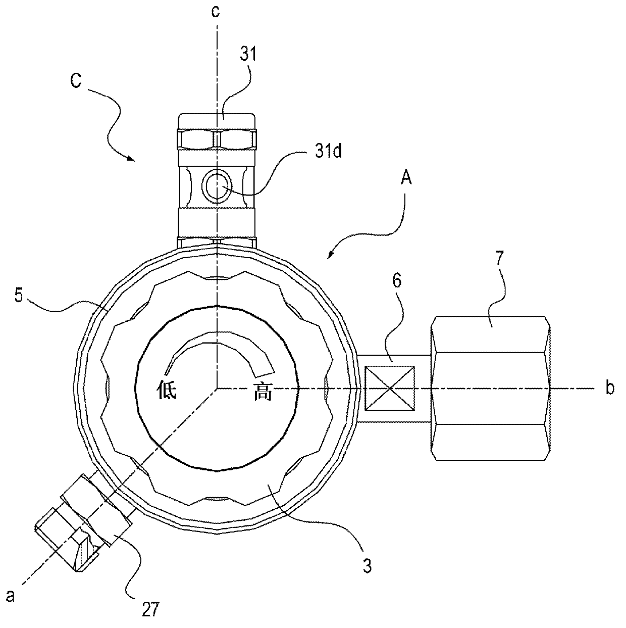
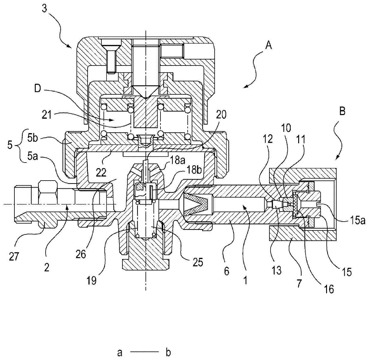
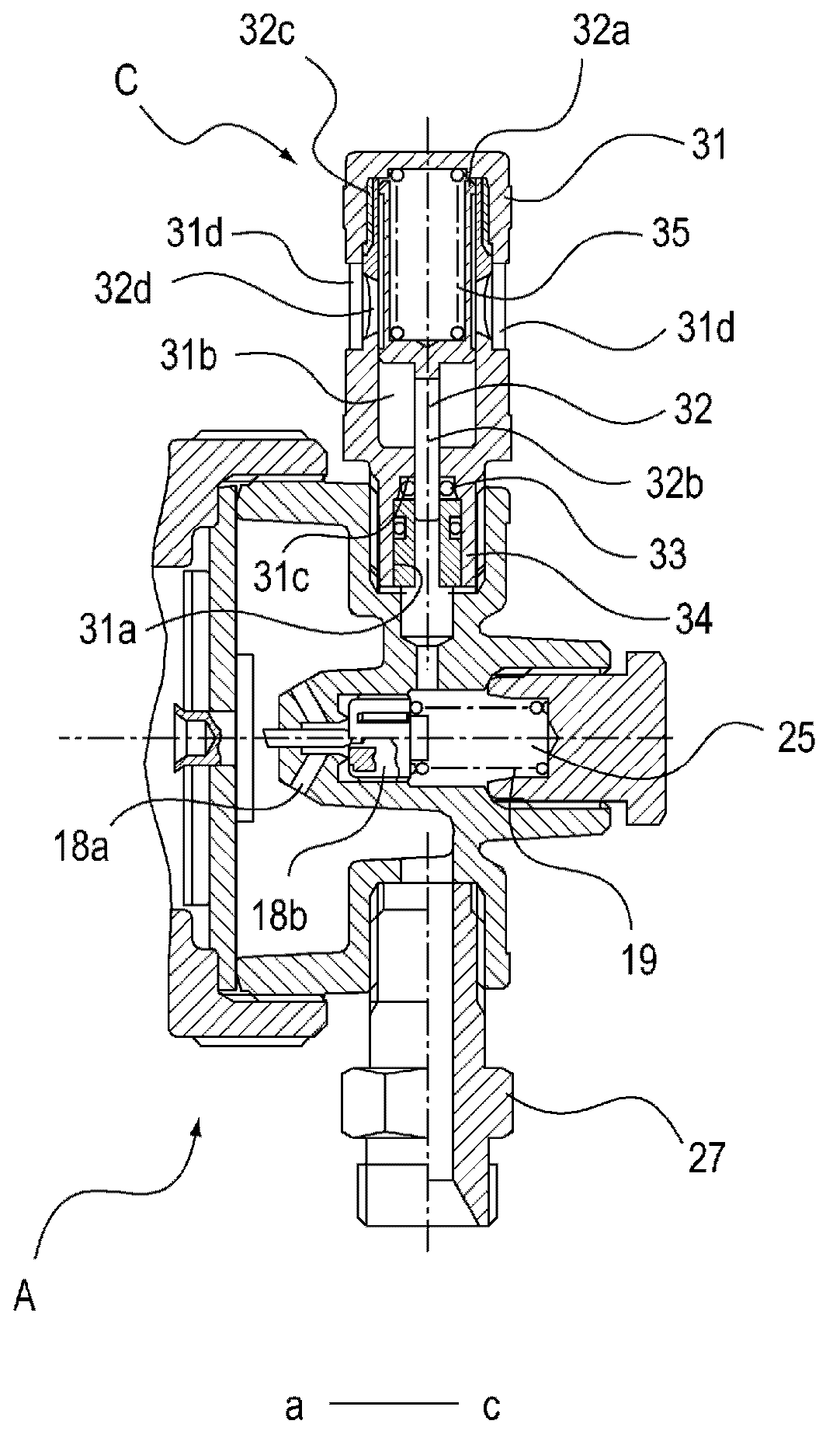
[0080] use Figure 1 ~ Figure 4 The structure of the pressure regulator of this embodiment will be described.

[0081] First, the structure of the pressure regulator A will be briefly described. This pressure regulator A is configured as an oxygen supplier for supplying medical oxygen to a patient, and is detachably attached to a medical oxygen cylinder (not shown) as a supply source of primary gas having a relatively high pressure. . Furthermore, this pressure regulator A can decompress high-pressure oxygen (primary gas) supplied from an oxygen cylinder into low-pressure oxygen (secondary gas), and the secondary gas can be supplied to a patient through an oxygen mask and a cannula.

[0082] Such as Figure 1 ~ Figure 3 As shown, the pressure regulator A has a primary side passage 1 , an adiabatic compression preventing mechanism B and a pressure indicating mechanism C, a secondary side passage 2 , a decompression mechanism D and an operating member 3 . The primary side pa...


PUM


Abstract

Provided is a pressure regulator comprising an adiabatic compression preventing mechanism and a pressure indicating mechanism. A pressure regulator comprises an adiabatic compression preventing mechanism (B) and a pressure indicating mechanism (C). The adiabatic compression preventing mechanism (B) comprises: a partitioning member (11) slidably disposed on a stepped part (10) at a primary-side passage (1) of the pressure regulator (A), the partitioning member (11) including a central small flow passage (11a) and a circumferential large flow passage (11f), the large flow passage being blocked when the partitioning member (11) makes contact with the stepped part (10), the partitioning member (11) further including a connection passage (17) formed at a downstream side of an upstream-side end surface (11d) so as to connect the small flow passage and the large flow passage; and a first spring (12) urging the partitioning member toward an upstream side in a gas flow direction. The pressure indicating mechanism (C) comprises: a cylindrical part (31) in which a first relief chamber (31a) having a small diameter and a second relief chamber (32b) having a large diameter are formed with an opening (31d) crossing the second relief chamber; a sliding member (32) including an indicating part (32a) and a pressure receiving part (32b), the sliding member (32) being slidably inserted in the cylindrical part (31); an O-ring (33) disposed on an end part of the first relief chamber; and a second spring (35) urging the sliding member toward the pressure receiving part.

Description

technical field [0001] The present invention relates to a pressure regulator capable of preventing adiabatic compression that occurs when primary gas having a relatively high pressure is supplied from a supply source, and capable of indicating pressure reduction of primary gas or presence or absence of supply without using a pressure gauge. Background technique [0002] For example, when a high-pressure gas (high-pressure gas) is supplied to an atmospheric pressure system with a closed end or a portion with a reduced cross-sectional area, the temperature of the supplied high-pressure gas will rise due to adiabatic compression. When the high-pressure gas is a pyrophoric gas such as oxygen, the temperature rise of the gas may adversely affect piping, valves, etc. constituting the system. [0003] A typical example of such a system is a pressure regulator. The pressure regulator has: a primary side connecting portion connected to a supply source of high-pressure gas including ...

Claims


Application Information

Patent Timeline
Patent Type & Authority Applications(China)
IPC IPC(8): G05D16/06F16K17/30F16K37/00
CPCF16K17/30F16K37/0066G05D16/0663F16K37/00G05D16/06
Inventor 神户敏生坪子寿水野成司高桥正男
Owner KOIKE SANSO KOGYO CO LTD
Why Eureka
Try Eureka