Spout-type die rotary device

A rotary die and chute technology, applied in the field of chute-type rotary die position device, can solve the problems of high cost, complex structure, troublesome installation, etc., and achieve the effects of simple operation, avoiding troublesome operation, and convenient combination.

Inactive Publication Date: 2013-09-18
WUXI DEHUA MACHINERY
View PDF8 Cites 3 Cited by
  • Summary
  • Abstract
  • Description
  • Claims
  • Application Information

AI Technical Summary

Problems solved by technology

In the prior art, when the mold is rotated, the upper mold lifting cylinder and the lower mold lifting cylinder are respectively installed in the upper mold assembly, and the lower mold lifting cylinder is installed in the lower mold assembly, and the two cylinders act synchronously to drive the upper mold assembly and the lower mold assembly. Synchronous work, its stability is good, but the structure is complicated, the installation is troublesome, and the cost is high

Method used


Image

  • Spout-type die rotary device
  • Spout-type die rotary device
  • Spout-type die rotary device

Examples


Embodiment Construction

[0028] The specific implementation manner of the present invention will be described below in conjunction with the accompanying drawings.

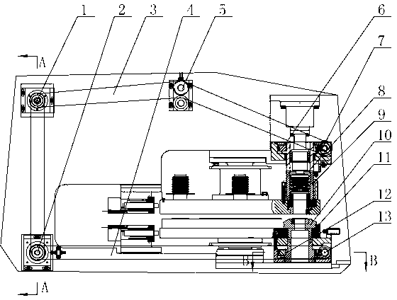
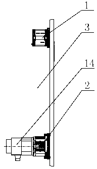
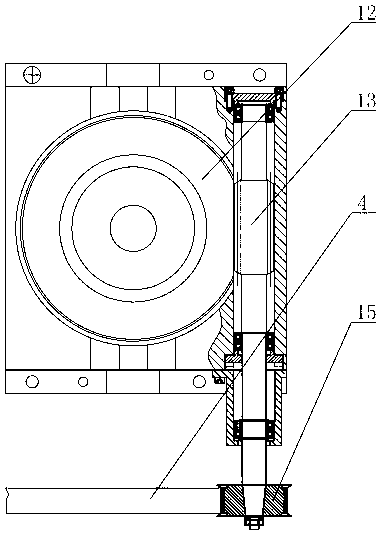
[0029] Such as figure 1 , figure 2 , image 3 with Figure 4 As shown, the chute-type rotary die positioning device of this embodiment includes a motor 14, and two synchronous belts are output on the output shaft of the motor 14, and the first synchronous belt 3 passes through the second synchronous pulley group 2 and passes through the first synchronous pulley Group 1 is connected to the upper mold assembly, the second synchronous belt 4 is connected to the lower mold assembly through the second synchronous pulley group 2, and the upper mold assembly and the lower mold assembly are connected coaxially: the structure of the upper mold assembly is: including the upper mold worm 7 , the upper die worm gear 6 meshed with the upper die worm 7, the upper drive sleeve 8 is installed coaxially with the upper die worm gear 6, and the lower par...


PUM


Abstract

The invention discloses a spout-type die rotary device which comprises a motor, wherein two synchronous belts are outputted by the output shaft of the motor; a first synchronous belt passes through a first synchronous belt wheel set to connected with an upper die component through a second synchronous belt wheel set; a second synchronous belt is connected with a lower die component through the second synchronous belt wheel set; the upper die component is coaxially connected with the lower die component; the upper die component structurally comprises an upper die worm and an upper die worm wheel meshed with the upper die worm; an upper transmission sleeve is coaxially mounted with the upper die worm wheel; an upper die sleeve is clamped at the lower part of the upper transmission sleeve; the lower die component structurally comprises a lower die worm and a lower die worm wheel meshed with the lower die worm; a lower transmission sleeve is coaxially mounted with the lower die worm wheel; a lower die holder is clamped at the upper part of the lower transmission sleeve. The spout-type die rotary device has a reasonable structure, is easy and simple to operate, avoids the troublesome operation in the prior art that an air cylinder is needed to control, reduces the cost, and improves the working efficiency.

Description

technical field [0001] The invention relates to a rotating device of a mold in mechanical processing, in particular to a chute-type rotating mold position device. Background technique [0002] The CNC turret punch press adopts the connecting rod mechanism or hydraulic pressure as the power. It is an efficient and highly automated sheet metal processing equipment. It is widely used in sheet metal processing equipment that processes more standard holes and more complex special-shaped holes on the same sheet. Rotary molds The device is more and more widely used because it can process holes with any angle by the punching machine. It is composed of active part, transmission tension part and rotating mechanism. The active part and the transmission tension part are the basic structures for power transmission, and the rotating mechanism is a device for controlling the angle of any punched angular hole. In the prior art, when the mold is rotated, the upper mold lifting cylinder is ...

Claims


Application Information

Patent Timeline
Patent Type & Authority Applications(China)
IPC IPC(8): B21D28/36
Inventor 肖德华赵建勋刘万兵吴前花
Owner WUXI DEHUA MACHINERY
Why Eureka
Try Eureka