Self-lubrication cooled type gear shaper spindle structure

An automatic lubricating and cooling technology, used in metal processing machinery parts, maintenance and safety accessories, metal processing equipment, etc., can solve the problems of locked spindle sleeve, large force, insufficient lubrication, etc., to prevent spindle wear and tear. , Small thermal deformation, the effect of preventing the spindle from grinding to death

Active Publication Date: 2013-09-18
宜昌长机科技有限责任公司
View PDF8 Cites 10 Cited by
  • Summary
  • Abstract
  • Description
  • Claims
  • Application Information

AI Technical Summary

Problems solved by technology

However, due to the fact that the main shaft is always moving, and the gap between the main shaft and the main shaft sleeve is small, the force is large, the lubrication is insufficient, and the temperature is long and fast, the main shaft is easy to pull the main shaft sleeve and lock the main shaft.
Especially on the gear shaping machine, due to the up and down reciprocating impact movement of the main shaft, the damage of the main shaft will make the tooth direction and tooth shape accuracy of the workpiece out of tolerance, and the tool will be directly damaged when the main shaft is locked.

Method used


Image

  • Self-lubrication cooled type gear shaper spindle structure
  • Self-lubrication cooled type gear shaper spindle structure
  • Self-lubrication cooled type gear shaper spindle structure

Examples


Embodiment Construction

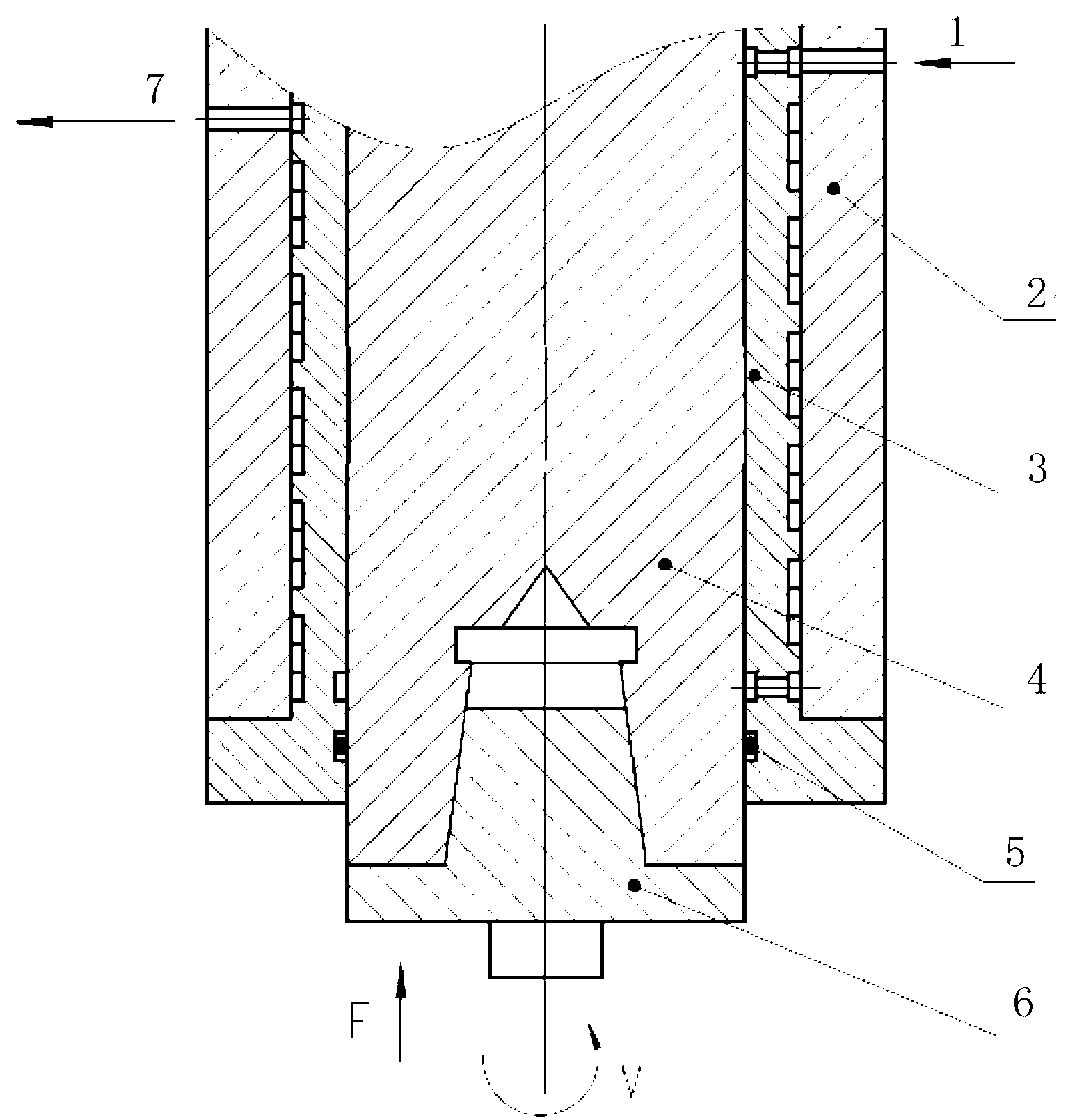
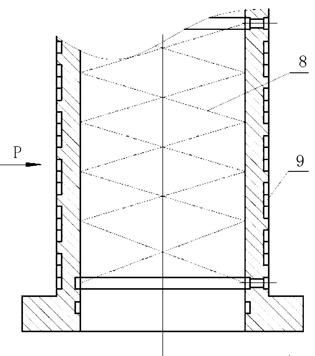
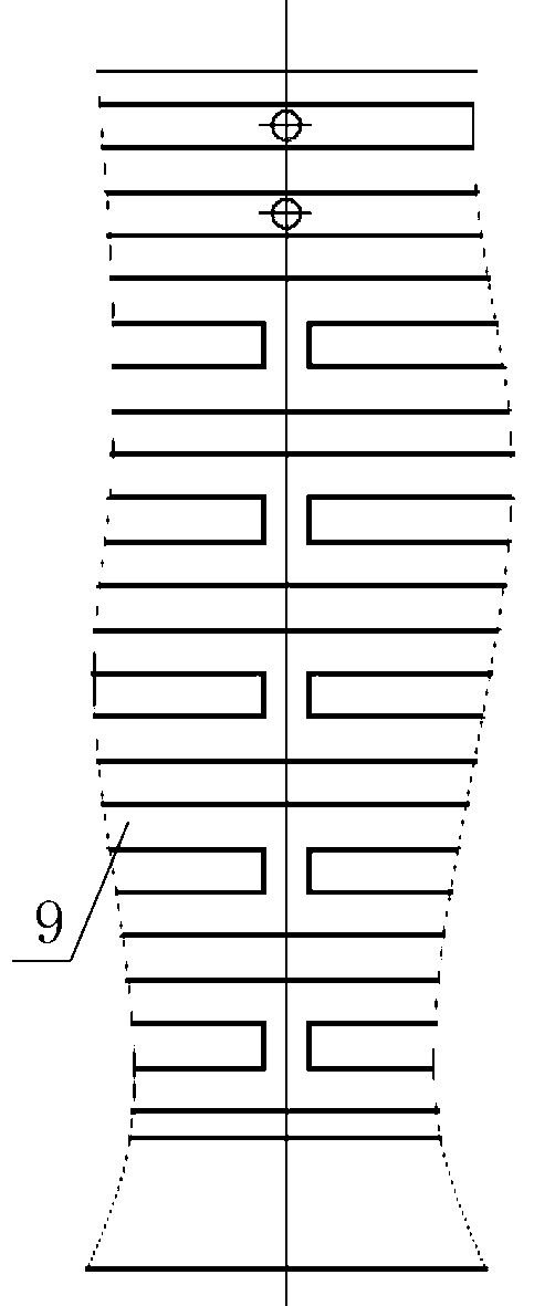
[0014] The structure of the present invention is as figure 1 As shown in -3, an automatic lubricating and cooling type gear shaper spindle structure, which includes a spindle 4, one end of the spindle is provided with a hanging tool sleeve 6, and the outside of the spindle 4 is provided with a spindle sleeve 3, and the spindle 4 moves up and down inside the spindle sleeve 3 and rotating movement, the main shaft sleeve 3 is embedded in the tool holder body 2, and the upper end of the main shaft sleeve 3 is respectively provided with an oil inlet 1 and an oil outlet 7, and the main shaft sleeve 3 is provided with a spiral oil groove 8, and the outer circle of the main shaft sleeve 3 There are multiple annular cooling grooves 9, and the lower end of the annular cooling grooves 9 communicates with the spiral oil groove 8. The main shaft 4, the main shaft sleeve 3, the tool holder body 2, the oil inlet 1 and the oil outlet 7 form a closed oil circulation system. There is clearance ...


PUM


Abstract

A self-lubrication cooled type gear shaper spindle structure comprises a spindle, wherein a spindle sleeve is arranged outside the spindle, and is embedded in a tool rest body; an oil inlet and an oil inlet are formed in the upper end of the spindle sleeve; spiral oil grooves are formed in the spindle sleeve; a plurality of ring-shaped cooling grooves are distributed on the excircle of the spindle sleeve; and the lower ends of the ring-shaped cooling grooves are communicated with the spiral oil grooves. According to the invention, the two spiral oil grooves are formed in the spindle sleeve, depending on the reciprocating movement of the spindle, oil is introduced into a friction zone to form a lubricating oil film so as to realize the purpose of lubrication and prevent grinding damage of the spindle; as the ring-shaped cooling grooves are distributed on the excircle of the spindle sleeve, and the lower ends of the ring-shaped cooling grooves are communicated with the spiral oil grooves, only one pair of openings are communicated between every two ring-shaped cooling grooves, and are distributed symmetrically, the lubricating oil flows to each cooling groove in the return process to take away heat of the spindle sleeve, which is generated by friction and impacting, so that the spindle sleeve is ensured to be fully cooled, the thermal deformation of the spindle sleeve becomes very small, and the grinding die of the spindle can be prevented.

Description

technical field [0001] The patent of the present invention relates to the main shaft structure of a gear shaping machine, in particular to a main shaft structure of a gear shaping machine with main shaft rotation and reverse movement. Background technique [0002] On the existing gear shaping machines and many large-scale equipment, the main shaft is often used directly as the main motion for transmitting high power, with high rotation speed, fast reverse motion and high precision. However, since the main shaft is always moving, and the gap between the main shaft and the main shaft sleeve is small, the force is large, the lubrication is insufficient, and the temperature rises rapidly, the main shaft is easy to pull the main shaft sleeve and lock the main shaft. Especially on the gear shaping machine, due to the up and down reciprocating impact movement of the main shaft, the damage of the main shaft will make the tooth direction and tooth shape accuracy of the workpiece out ...

Claims


Application Information

Patent Timeline
Patent Type & Authority Applications(China)
IPC IPC(8): B23B19/02B23Q11/12
Inventor 罗成
Owner 宜昌长机科技有限责任公司
Why Eureka
Try Eureka