Wing load applying device for large aircraft strength test

A technology of aircraft strength and application device, which is applied in the field of aviation fatigue test, can solve the problems of long fatigue test cycle, affecting the load balance of the whole aircraft, and slow loading speed, so as to improve the accuracy of loading and assessment, avoid distortion of assessment, and reduce difficulty Effect

Active Publication Date: 2013-09-18
XIAN AIRCRAFT DESIGN INST OF AVIATION IND OF CHINA
View PDF1 Cites 25 Cited by
  • Summary
  • Abstract
  • Description
  • Claims
  • Application Information

AI Technical Summary

Problems solved by technology

At present, the loading of the wing in the strength test mainly adopts the loading actuator fixed on the floor or the ceiling. This fixed loading actuator can only be designed and arranged according to one load situation in the fatigue test, generally under the cruising 1g load. The deformation arrangement of the wing, this arrangement has a large error in the application of loads under other load conditions, especially the load application under ground load conditions, which affects the test loading and assessment accuracy; on the other hand, due to the wing load The error in the applied direction also affects the balance of the whole machine load, and uncontrollable forces and moments will be generated in the structure of the parts constrained by the whole machine test during the alternating process of peaks and valleys of the test load, thus affecting the assessment results of these parts; in addition , due to the large deformation of the wing, a special loading actuator with a stroke of more than three meters is required to load the outer wing in the traditional way, which brings difficulties in the implementation of the test. If two actuators are used in series to load, because The loading speed of the test in series is very slow, which will lead to a long cycle of fatigue test

Method used


Image

  • Wing load applying device for large aircraft strength test
  • Wing load applying device for large aircraft strength test

Examples


Embodiment Construction

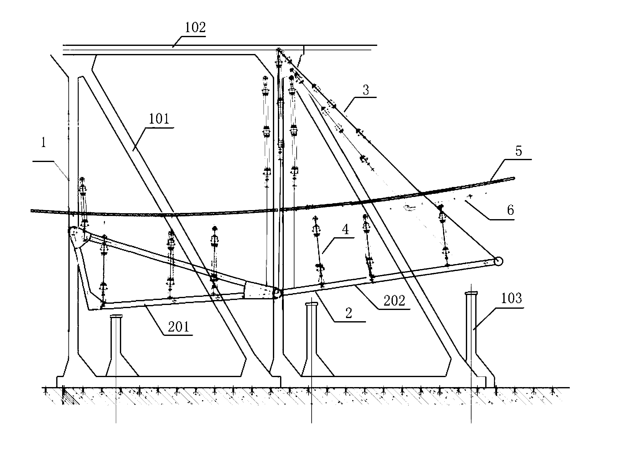
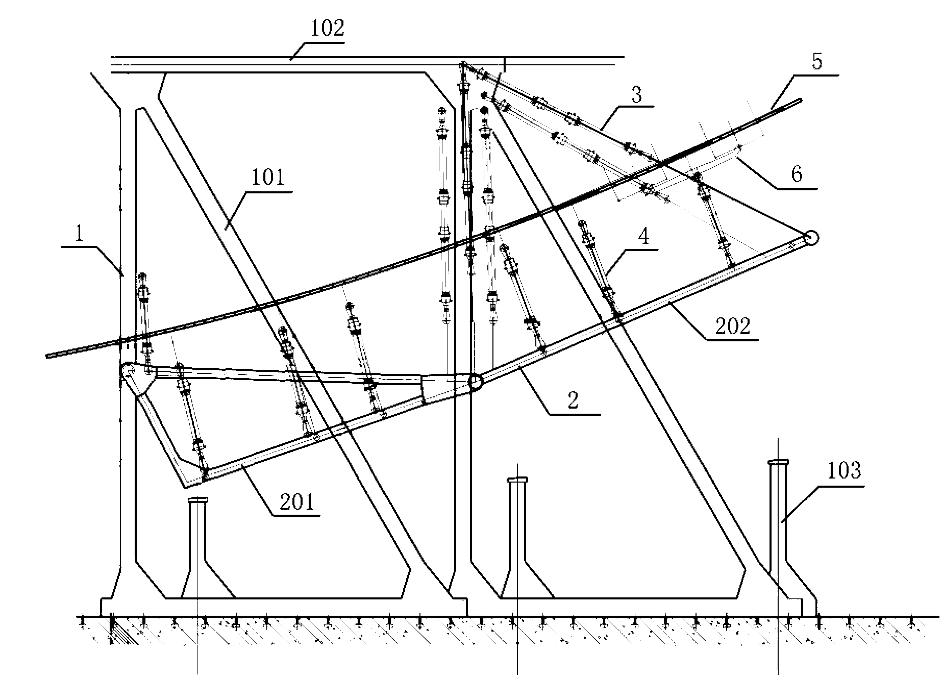
[0012] Below in conjunction with accompanying drawing the present invention is described in further detail, please refer to figure 1 and figure 2 .

[0013] Such as figure 1 Shown is a schematic diagram of the structure of the present invention.

[0014] A large-scale aircraft strength test wing load application device, including a pillar system 1, a loading platform 2, several platform moving actuators 3 and several loading actuators 4, the loading platform 2 consists of a tripod 201 and a flat plate 202 The other end of the triangular bracket 201 is hinged on the pillar system 1, and several platform moving actuators 3 are hinged on the triangular bracket 201, and the other end of the platform moving actuator 3 is hinged on the pillar system 1. One end of the several loading cylinders 4 is hinged on the loading platform 2, and the other end is hinged on the wing 5.

[0015] The pillar system 1 is composed of more than two triangular pillars 101 and crossbeams 102 , and ...


PUM


Abstract

The invention belongs to the field of aviation fatigue tests, and particularly relates to a wing load applying device for a large aircraft strength test. The wing load applying device comprises a brace system, a loading platform, a plurality of platform move actuator cylinders and a plurality of loading actuator cylinders. According to the wing load applying device, through the controllable adjustment of platform positions of the movable loading platform controlled by a computer according to wing deformation of load during aircraft stopping on ground and below 1 g load during flying, as well as the loading by the actuator cylinders arranged on the platform, load applying directions and values under the situation of large deformation of large aircraft wings are ensured, so that test loading and test precision are improved; through the accurate applying of wing load, balance of a conventional whole aircraft test is ensured, so that inaccurate structure test of constraint components, which is caused by unbalance of load is avoided; and the loading of wings under large deformation can be realized by using conventional actuator cylinders, and large-stroke special actuator cylinders and tandem actuator cylinders can be omitted, so that the experiment implementation difficulty is reduced and a test cycle is ensured.

Description

technical field [0001] The invention belongs to the field of aviation fatigue tests, in particular to a wing load applying device for large-scale aircraft strength tests. Background technique [0002] The wingspan of a large aircraft is large, and there is a relatively large displacement from the outer wing to the wingtip after the wing is loaded in the strength test (generally about 3m). Considering the deformation of the wing, how to accurately simulate the applied force in the test? Wing loading is a technical difficulty. At present, the loading of the wing in the strength test mainly adopts the loading actuator fixed on the floor or the ceiling. This fixed loading actuator can only be designed and arranged according to one load situation in the fatigue test, generally under the cruising 1g load. The deformation arrangement of the wing, this arrangement has a large error in the application of loads under other load conditions, especially the load application under ground...

Claims


Application Information

Patent Timeline
Patent Type & Authority Applications(China)
IPC IPC(8): B64F5/00B64F5/60
Inventor 王新波宁宇张志楠
Owner XIAN AIRCRAFT DESIGN INST OF AVIATION IND OF CHINA
Why Eureka
Try Eureka