
Buoyancy valve, washing system and engineering machine

A technology of buoyancy valves and buoyancy chambers, which is applied to mechanical equipment, valve details, multi-way valves, etc., can solve the problems of not being able to determine whether there is still water in the washing pipeline, and the effect of emptying cannot be guaranteed, so as to reduce rust Or the probability of being damaged by freezing, the effect of improving the service life and user experience

Active Publication Date: 2013-09-18
SANY AUTOMOBILE MFG CO LTD
View PDF8 Cites 4 Cited by
  • Summary
  • Abstract
  • Description
  • Claims
  • Application Information

AI Technical Summary

Problems solved by technology

In the actual application process, the existing water washing system cannot determine whether there is still accumulated water in the water washing pipeline, so the effect of emptying cannot be guaranteed

Method used


Image

  • Buoyancy valve, washing system and engineering machine
  • Buoyancy valve, washing system and engineering machine
  • Buoyancy valve, washing system and engineering machine

Examples


Embodiment Construction

[0024] It should be noted that the embodiments of the present invention and the features of the embodiments may be combined with each other under the condition of no conflict. The following will be combined with the Figures 1 to 6 Specific embodiments of the present invention will be described in detail.

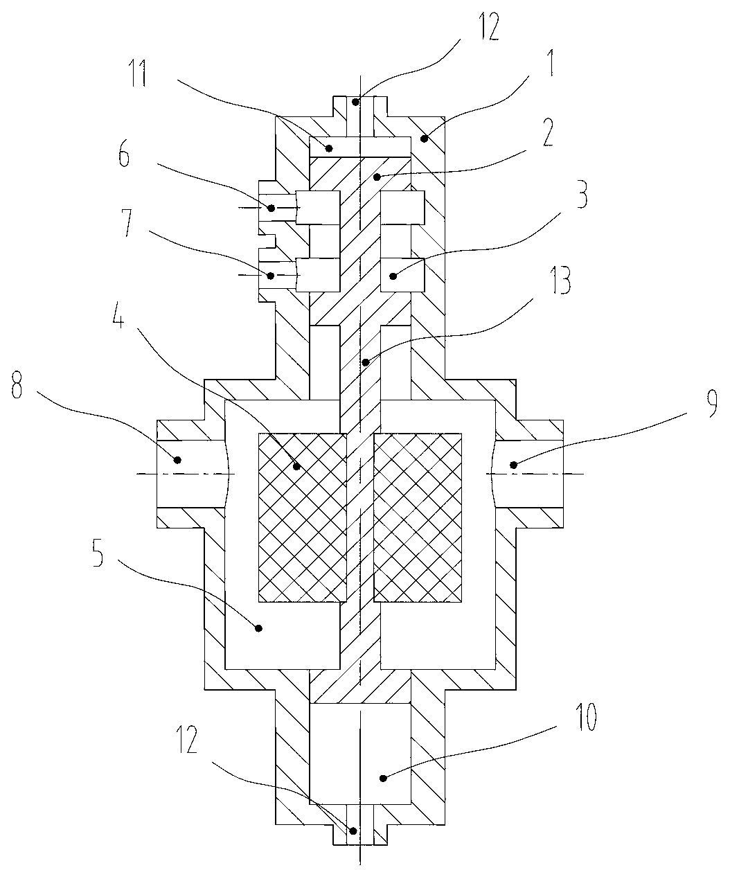
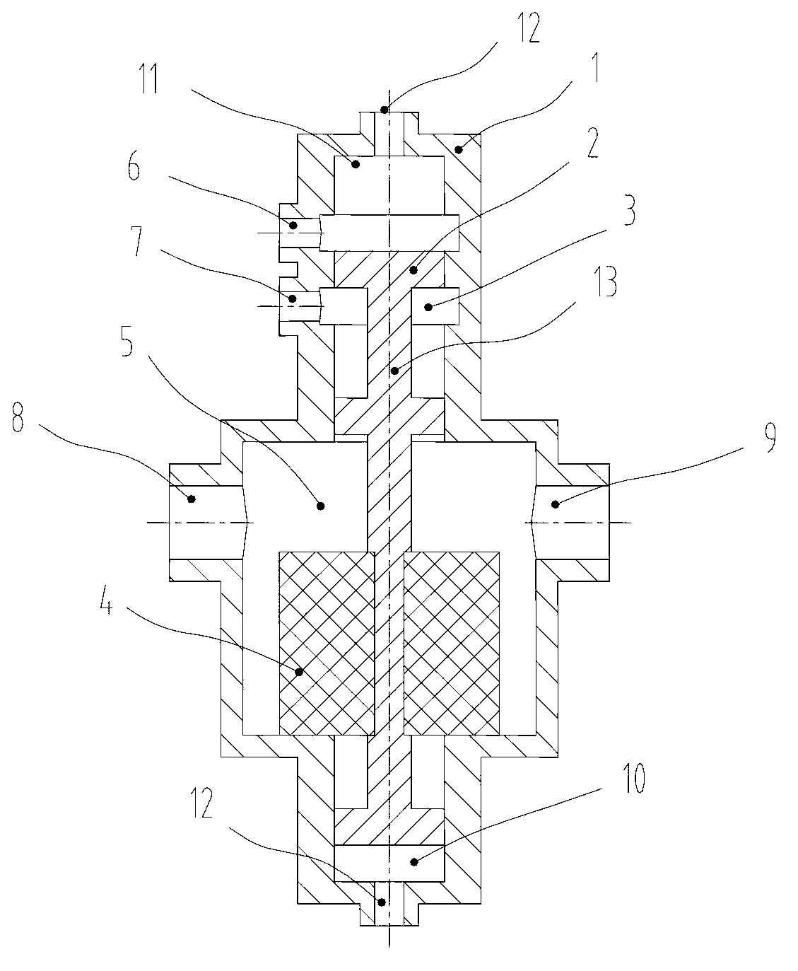
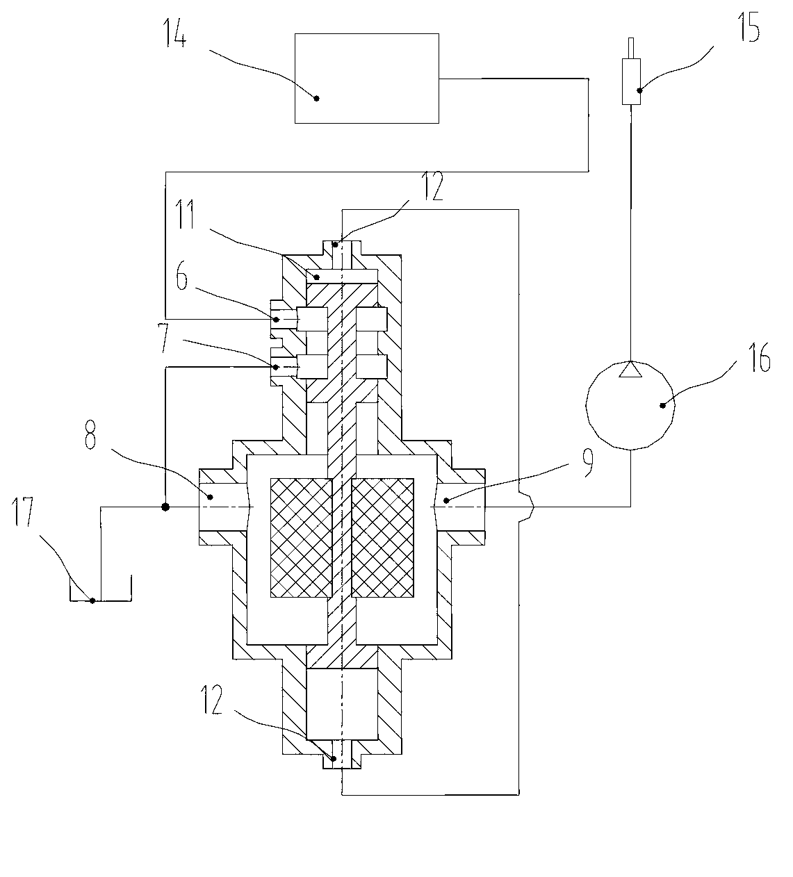
[0025] figure 1 A schematic structural diagram of a buoyancy valve in a floating state proposed by a specific embodiment of the present invention; figure 2 for figure 1 The structure diagram of the shown buoyancy valve in the initial state; image 3 A schematic structural diagram of a water washing system proposed by a specific embodiment of the present invention; Figure 4 A schematic structural diagram of another water washing system during water washing proposed by a specific embodiment of the present invention; Figure 5 for Figure 4 Schematic diagram of the structure of the shown washing system when it is draining; Image 6 for Figure 4 Schematic diagram of ...


PUM


Abstract

The invention provides a buoyancy valve. The buoyancy valve comprises a valve body, wherein a valve cavity and a buoyancy cavity are arranged inside the valve body; a valve core is arranged inside the valve cavity; a floater is arranged inside the buoyancy cavity, and is connected with a core shaft of the valve core; a first port, a second port, a third port and a fourth port are arranged on the valve body; the first port and the second port are communicated with the valve cavity; the third port and the fourth port are communicated with the buoyancy cavity; the floater has an original state and a floating state; when the floater is at the original state, the buoyancy valve switches off the first port and the second port; when the floater is located at the floating state, the buoyancy valve is communicated with the first port and the second port. The buoyancy valve can be used for identifying when the emptying operation is completed, so that the emptying effect can be effectively ensured, and the service life and the user experience of a washing system can be improved. Furthermore, the invention further provides the washing system with the buoyancy valve and an engineering machine.

Description

technical field [0001] The invention relates to construction machinery, in particular to a buoyancy valve; in addition, it also relates to a water washing system and construction machinery with the buoyancy valve. Background technique [0002] At present, construction machinery has been widely used in various construction operations, which has brought great convenience to construction. Many construction machinery (such as concrete pumping equipment, mixer trucks, etc.) often need to be partially cleaned after the operation is completed. For this reason, these construction machinery are usually provided with a water washing system. [0003] In order to prevent the adverse effects of accumulated water on the water washing system, such as causing rust or freezing in a cold environment and then freezing the water pump, it is usually necessary to empty the water after the completion of the water washing operation. The existing emptying method is mainly manual air pressure emptyi...

Claims


Application Information

Patent Timeline
IPC IPC(8): F16K11/044F16K31/20F16K33/00F16K27/02B08B3/02
Inventor 贾海云付劲松赵勇
Owner SANY AUTOMOBILE MFG CO LTD
Learn More