Fixing structure of led light bar socket

A technology of LED light bar and fixed structure, which is applied in the direction of light source fixing, lighting device parts, lighting device, etc. Assembly efficiency, reducing the number of wire harnesses, and simplifying the effect of connection methods

Active Publication Date: 2015-08-19
SICHUAN CHANGHONG ELECTRIC CO LTD
View PDF6 Cites 0 Cited by
  • Summary
  • Abstract
  • Description
  • Claims
  • Application Information

AI Technical Summary

Problems solved by technology

Since the LED light strip and the LED light strip socket are all processed by SMD, the LED light strip is more convenient in production. However, due to the large number of LED light strips, each LED light strip has at least one LED light strip socket. During the production of the module, since the wire harness needs to be extended into the module, and there are many wiring harnesses in the module, the operation is inconvenient, and the LED light bar is easy to be damaged, the production line operation efficiency is low, and the reliability is reduced
The front structure of the backlight module is as follows: figure 2 , there are wires 16 inside the module, and the wire harnesses of each LED light bar on the front of the PCB board are respectively connected to the corresponding LED light bar sockets 12, which may easily cause poor assembly of the device

Method used


Image

  • Fixing structure of led light bar socket
  • Fixing structure of led light bar socket
  • Fixing structure of led light bar socket

Examples


Embodiment 1

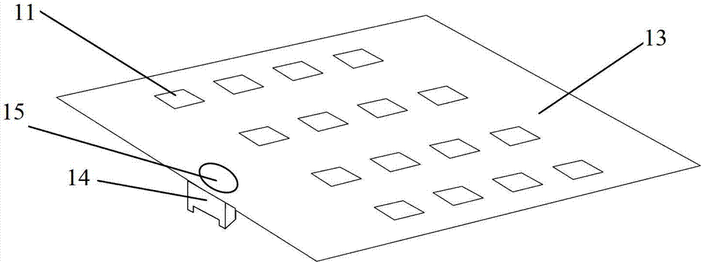
[0025] Such as Figure 4 Shown is a schematic cross-sectional view of the plug-in type LED light bar socket 14 of this example. In this embodiment, the LED light bar socket 14 is reversely welded on the PCB board 13 by hand or special equipment to strengthen its connection with the PCB board 13. connection reliability. On the PCB board 13, there is a small hole 15 at the position corresponding to the LED light bar socket 14. After the LED light 11 is fixed, the LED light 11 can be connected to the LED light bar socket 14 with a wire from the outside of the backboard, and the LED light can also be connected. Bar socket 14 is connected with external power supply through aperture 15. It can be seen from the figure that the LED light bar socket 14 includes a connecting piece 141 on the front side of the PCB 13 and a connecting piece 142 on the back side of the PCB 13 . In practical applications, the LED light can be connected to the socket through the small hole 15 and the conne...

Embodiment 2

[0029] Such as Figure 5 , in this embodiment, the LED light bar socket 14 is reversely mounted on the PCB board 13 through a placement machine or a tooling fixture, and the LED light bar socket 14 and the LED light 11 are respectively fixed on both sides of the PCB board 13. Through this structure There is no need to consider wiring harness connections when installing LED strips. The connection between the LED light strip socket 14 and the external power supply board is realized through the part of the LED light strip socket 14 on the back of the PCB 13 , and the connection with the light strip is realized through the connecting piece 141 on the front of the PCB 13 . After the light bar and internal parts are assembled, the light bar wiring harness can be directly connected to the light bar and power supply on the back of the module when the whole machine is assembled, which simplifies the connection of the light bar to the wiring harness interface on the back of the module a...


PUM


Abstract

The invention relates to a liquid crystal backlight display technology, solves the technical problem that the quantity of wire harnesses in a backlight module are large in the prior art, and provides a fixing structure for an LED light bar socket. The technical scheme adopted to solve the technical problem is that the fixing structure comprises a PCB (13), an LED lamp (11), an LED light bar socket (14) and a lead wire, wherein the LED lamp (11) is fixed on the front side of the PCB (13); a small hole for the lead wire to pass through is formed in the PCB (13); and the position of the LED light bar socket (14) corresponds to that of the small hole (15). The fixing structure has the beneficial effects that through the optimization of the fixing manner of the LED light bar socket, the quantity of wire harnesses in the backlight module is reduced, the connection mode of the light bar socket is simplified, the production line assembling efficiency is improved, and the fixing structure is suitable for a direct type LED backlight module.

Description

technical field [0001] The invention relates to liquid crystal backlight display technology, in particular to a fixing structure for an LED light bar socket in a backlight module. Background technique [0002] In the direct-type LED backlight liquid crystal module, the LED light bar as the light source is fixed on the back panel of the module, and the backlight module can obtain a surface light source with uniform light through the cooperation of optical films such as a diffusion plate. [0003] In common direct-type liquid crystal module products, in order to facilitate the production of LED light strips, in direct-type backlight modules, LED lights are generally processed into multiple small-sized units to form LED light strips, and then assembled to form a large LED light strip. Backlight. At present, the electrical interface for lighting LEDs is mainly a traditional surface mount type socket. Such as figure 1 As mentioned above, the LED lamp 11 is fixed on one side of...

Claims


Application Information

Patent Timeline
Patent Type & Authority Patents(China)
IPC IPC(8): F21V19/00G02F1/13357F21Y101/02
Inventor 杨伟茂谢波陈宗辉杨光
Owner SICHUAN CHANGHONG ELECTRIC CO LTD
Why Eureka
Try Eureka