
Clamping device for plant leaf surface physical parameter detection sensor

A technology for detecting sensors and physical parameters, applied in measuring devices, instruments, scientific instruments, etc., can solve the problems that affect the measurement accuracy of measuring instruments, the front end is prone to opening, and the sensor is unreliable, so as to reduce damage to the measured object, Optimize the overall structure and the effect of reliable fixation

Inactive Publication Date: 2013-09-18
CHINA JILIANG UNIV
View PDF3 Cites 4 Cited by
  • Summary
  • Abstract
  • Description
  • Claims
  • Application Information

AI Technical Summary

Problems solved by technology

If such a fixture is used to clamp a relatively small, unbreakable and stable object to be measured, it is more feasible, but if it is used to clamp a measured object such as tobacco leaves, the volume of the fixture needs to be increased. In a changing state, the control of the clamping force is also an important factor. Finally, the tobacco leaves are easily damaged when they are dried and cannot bear a large weight. Larger size, extremely inconvenient to carry and install, narrow range of use
There is also a prominent disadvantage of the clamp clamp, that is, if the design of the clamp is not suitable, the front end is prone to open when clamping the object to be measured, so that the sensor cannot reliably contact the surface of the object to be measured, which affects the measurement accuracy of the measuring instrument

Method used


Image

  • Clamping device for plant leaf surface physical parameter detection sensor
  • Clamping device for plant leaf surface physical parameter detection sensor
  • Clamping device for plant leaf surface physical parameter detection sensor

Examples


Embodiment Construction

[0015] The present invention will be further described below in conjunction with accompanying drawing.

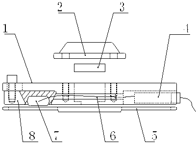
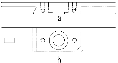
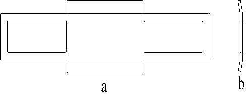
[0016] Such as figure 1 As shown, the present invention includes a splint one 1, a magnet cover plate 2, a magnet 3, a USB connector 4, a splint two 5, a wiring groove 6 and a trapezoidal pressing block 8; a stepped through hole is opened in the center of the splint one to place the magnet, Adjust the depth of the magnet according to the thickness of the added blade to achieve a suitable clamping force, and then seal it with a magnet cover and screws. In addition, there are protruding parts on both sides of the magnet cover, so that you can hold the first splint; the ladder of the first splint The peripheral side of the hole is in the shape of a half dovetail groove, and there is a rectangular groove on the splint corresponding to the end of the dovetail groove. The trapezoidal pressing block can freely adjust the position in the rectangular groove through screws, and the t...


PUM


Abstract

The invention discloses a clamping device for a plant leaf surface physical parameter detection sensor, aiming to overcome defects that existing clamping devices are large in size, inconvenient to carry and narrow in application range. A stepped through hole for holding a magnet is formed at the center of an upper clamping plate, a rectangular groove is formed at one end of the upper clamping plate, the depth of the stepped thorough hole is larger than the thickness of the magnet, the stepped through hole is sealed by a magnet cover plate, one side of the stepped through hole, close to the rectangular groove, is in the shape of a semi-dovetail groove, and a trapezoidal clamping block is regulated in the rectangular groove freely by screws, and matches with the semi-dovetail groove to fix the physical parameter acquisition sensor. Besides, an elongated slot is formed at the other end of the upper clamping plate and used for mounting a USB (universal serial bus) connector, and is communicated with a wiring slot on the inner side of the upper clamping plate, and the USB connector is in signal connection with the physical parameter acquisition sensor through a signal line in the wiring slot. By the clamping device, the sensor can be fixed reliably, measurement precision of leaf thermometers is improved, and damages to measured objects can be reduced to the utmost extent.

Description

technical field [0001] The invention relates to a sensor clamping device of a plant leaf surface physical parameter detector, relates to a test and measurement technology of a plant leaf temperature real-time detector, and particularly relates to a kind of tobacco leaf which is easy to be damaged during the baking process and has a leaf moisture The clamping temperature measurement technology of the measured object whose parameters such as thickness and thickness are constantly changing. Background technique [0002] Tobacco leaf curing technology is a crucial technical link in the production of high-quality tobacco leaves. The detection and control of the tobacco leaf surface and the temperature and humidity of the tobacco room are the prerequisites for improving the curing technology. Aiming at the present situation that the tobacco leaf curing temperature and humidity measuring instrument cannot directly measure the surface temperature of the tobacco leaf and has low meas...

Claims


Application Information

Patent Timeline
IPC IPC(8): G01K1/14G01K1/143
Inventor 胡佳成李东升郑志月刘月瑶宋旭
Owner CHINA JILIANG UNIV
Learn More