Annular cutting device

A kind of annular shearing and annular technology, which is used in measuring devices, using a stable shear force to test the strength of materials, instruments, etc. The problem of high maintenance cost, to achieve the effect of easy inspection and maintenance, low maintenance cost and low price

Inactive Publication Date: 2013-09-18
NORTHEAST GASOLINEEUM UNIV
View PDF4 Cites 12 Cited by
  • Summary
  • Abstract
  • Description
  • Claims
  • Application Information

AI Technical Summary

Problems solved by technology

[0005] At present, the annular shearing device developed internationally is mainly aimed at the determination of shear strength parameters of rock and soil movement, which cannot meet the requirements of applied pressure and device strength for geological process simulation, and cannot measure the permeability of the shear zone, and is expensive and maintains high costs.

Method used


Image

  • Annular cutting device
  • Annular cutting device
  • Annular cutting device

Examples


Embodiment Construction

[0022] Below in conjunction with accompanying drawing, the present invention will be further described:

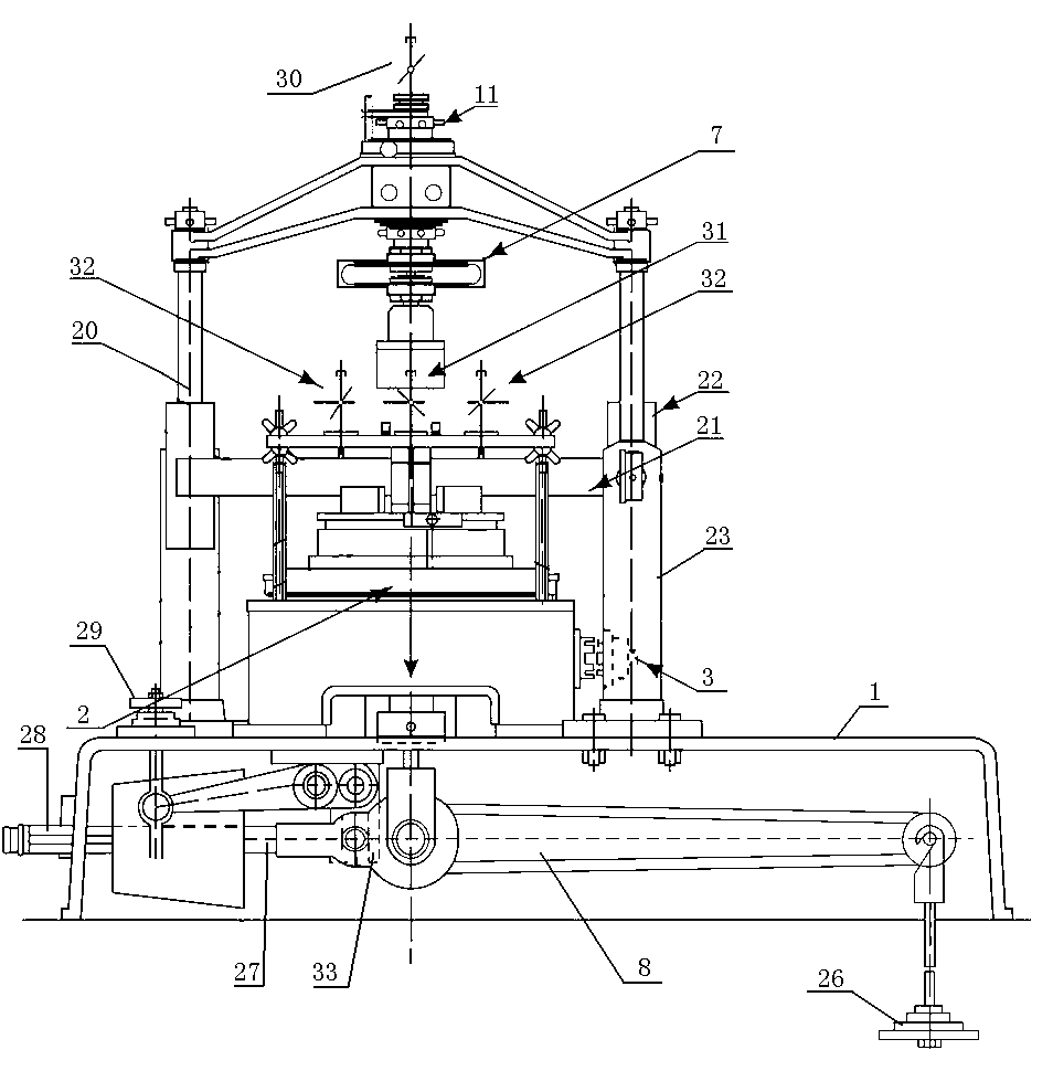
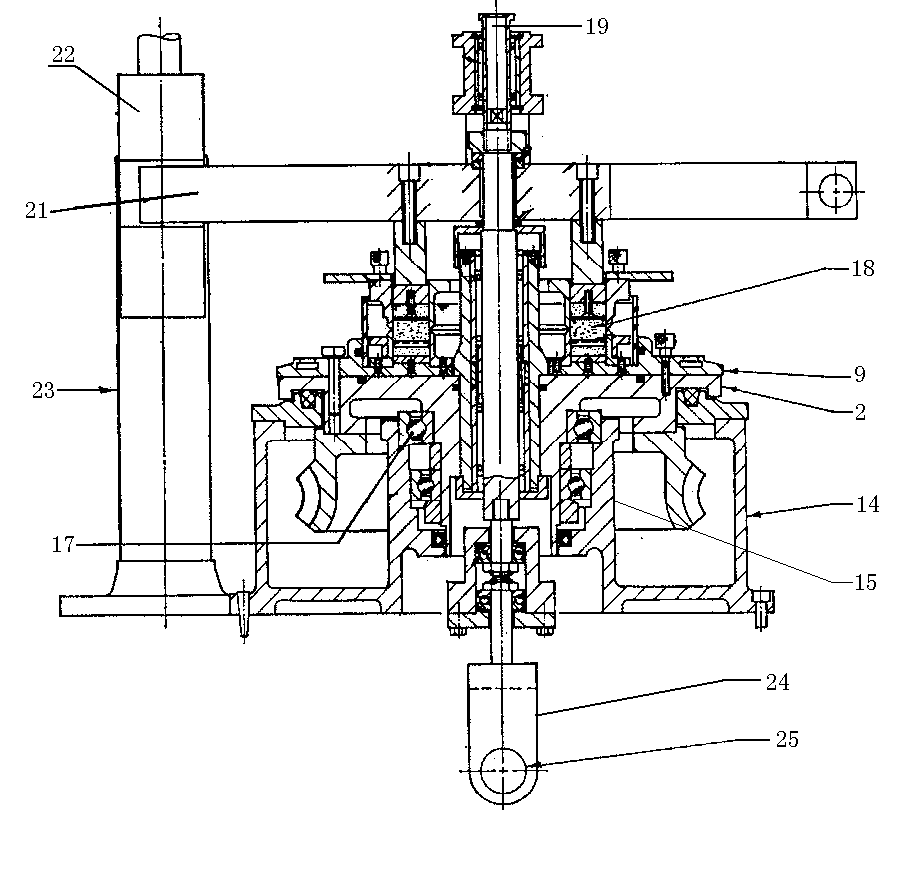
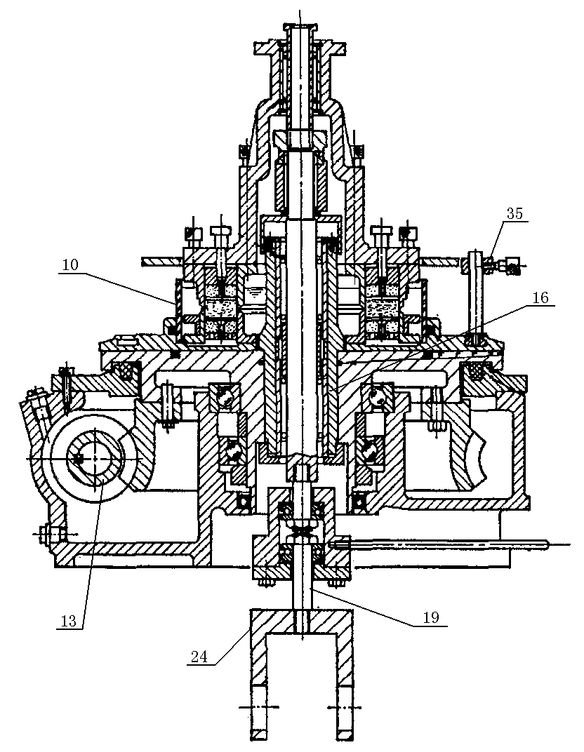
[0023] combine figure 1 , Figure 4 As shown, this annular shearing device includes a base 1, a rotary table 2, a rotary drive mechanism 3, an upper fixed ring 4, a lower fixed ring 5, a vertical loading mechanism, an annular loading plate 6, a force measuring ring 7, a tangential The load measuring ring 22, the rotating platform 2 is installed on the base 1, the rotating drive mechanism 3 is connected to the rotating platform 2, the annular chassis 9 is installed on the rotating platform 2, the plexiglass water tank 10 and the annular chassis 9 are fixedly connected as one, The lower fixing ring 5 is arranged at the bottom of the organic glass tank 10, and the bottom of the lower fixing ring 5 has a porous ceramic ring 12; the upper fixing ring 4 is arranged on the lower fixing ring 5 through a vertical loading mechanism, and the upper fixing ring 4 and the lower fixing ...


PUM


Abstract

The invention relates to an annular cutting device which comprises a base, a rotary table, a rotary drive mechanism, an upper fixing ring, a lower fixing ring and a vertical loading mechanism, wherein the rotary table is mounted on the base; the rotary drive mechanism is connected with the rotary table; an annular base plate is mounted on the rotary table; an organic glass water groove is fixedly connected with the annular base plate to form a whole body; the lower fixing ring is arranged at the bottom of the organic glass water tank; a porous ceramic ring is arranged at the bottom of the lower fixing ring; the upper fixing ring is arranged on the lower fixing ring through the vertical loading mechanism; a rock soil sample is arranged on the porous ceramic ring; an annular loading plate is pressed on the porous ceramic ring on the rock soil sample; the annular loading plate is connected with the vertical loading mechanism; the vertical loading mechanism comprises a load force arm, a central main shaft, a load bracket and a torque arm; the torque arm is transversely arranged in the load bracket; tangential load force measurement rings are mounted at two ends of the torque arm; the tangential load force measurement rings are adhered to the load bracket. According to the annular cutting device, rock soil movement cutting strength parameters can be accurately measured and easily detected, the price is low, and the maintenance expense is low.

Description

[0001] 1. Technical field: [0002] The invention relates to an experimental device for measuring the shear strength of rock and soil movement in the field of geotechnical engineering, in particular to an annular shearing device. 2. Background technology: [0003] The annular shear device is an indoor experimental device for basic geology, which is mainly used for the simulation of the formation process of mudstone smear and the determination of rock mechanical parameters in the underground environment. The annular shearing device can measure the change law of the corresponding rock shear strength with displacement growth before and after the formation of mudstone smear, and can meet the permeability measurement of mudstone smear under different fault distances. [0004] The ring shear test is a process in which the rock sample is put into the sample ring, and the vertical pressure is applied to the sample through the upper pressure plate, and on this basis, a certain torsio...

Claims


Application Information

Patent Timeline
Patent Type & Authority Applications(China)
IPC IPC(8): G01N3/24G01N3/02
Inventor 刘宗堡付晓飞孟令东孙永河赵淼张晓玲
Owner NORTHEAST GASOLINEEUM UNIV
Why Eureka
Try Eureka