Unlock instant, AI-driven research and patent intelligence for your innovation.

Magnetic detection device and manufacturing method thereof

Technology of a magnetic detection device and manufacturing method

Active Publication Date: 2013-09-18
ALPS ALPINE CO LTD
View PDF10 Cites 7 Cited by
  • Summary
  • Abstract
  • Description
  • Claims
  • Application Information

AI Technical Summary

Problems solved by technology

[0017] like Figure 8 As shown in (c) and (d), when the magnetic detection device 26 is installed in an oblique state with respect to the mounting substrate 27, the geomagnetic azimuth cannot be accurately detected by the geomagnetic sensor built in the magnetic detection device 26, thereby A decrease in detection accuracy or uneven detection accuracy occurs
[0018] In each of the above-mentioned patent documents, in the structure provided with a resist layer having an opening for exposing the electrode pad to the mounting surface, there is no disclosure for reducing the The structure of the mounting surface where the resist peels off or the solder paste flows out

Method used


Image

  • Magnetic detection device and manufacturing method thereof
  • Magnetic detection device and manufacturing method thereof
  • Magnetic detection device and manufacturing method thereof

Examples


Embodiment Construction

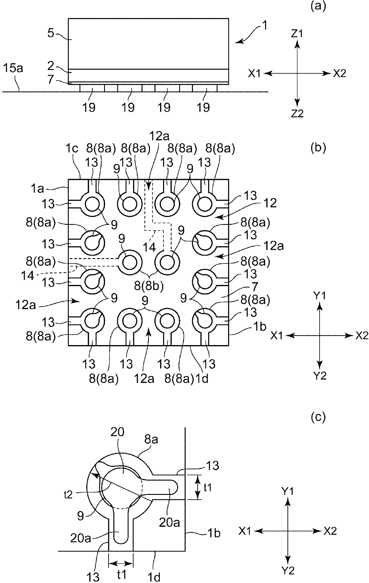
[0077] figure 1 (a) is a front view of the magnetic detection device in this embodiment, figure 1 (b) means figure 1 The rear view of the mounting surface of the magnetic detection device shown in (a), figure 1 (c) is to figure 1 (b) A partial enlarged rear view showing an enlarged part of the mounting surface. in addition, figure 2 (a) is an enlarged partial rear view showing peripheral openings and openings formed on the insulating layer of the mounting surface in this embodiment, especially for comparison with conventional systems without openings. Figures explaining the effects of this embodiment. in addition, figure 2 (b) is a partial rear view showing the shape of the peripheral opening in another embodiment. in addition, image 3 It is a partially enlarged vertical cross-sectional view showing the magnetic detection device in this embodiment and a state in which the magnetic detection device is mounted on a mounting substrate. in addition, Figure 4 It ...


PUM


Abstract

The object of the utility model is to provide a magnetic detection device and a manufacturing method thereof, wherein the magnetic detection device can be stably arranged parallely to an installation substrate. The magnetic detection device (1) is provided with a magnetic sensor used for detecting the direction of the external field and a plurality of electrode pads disposed on the installation surface. The magnetic detection device (1) is characterized in that an insulation layer (7) is disposed on the installation surface (12), and is provided with a plurality of openings (8); the plurality of pads are disposed in the plurality of openings (8); and opened parts (13), which are disposed in a plurality of peripheral opening parts (8a) of a peripheral part (12a) of the installation surface (12) in the plurality of the openings (8), and are communicated with side surfaces of the magnetic detection device from the peripheral opening parts (8a).

Description

technical field [0001] The present invention relates to the structure of, in particular, the mounting surface of a magnetic detection device including a magnetic sensor for detecting the direction of an external magnetic field. Background technique [0002] As a magnetic sensor for detecting the direction of an external magnetic field, for example, there is a geomagnetic sensor for detecting the orientation of earth magnetism. [0003] A magnetic detection device having a geomagnetic sensor is a device in which the geomagnetic sensor is provided on a substrate and packaged. The back side of the substrate is equivalent to the mounting surface for mounting with the mounting substrate, such as Figure 8 (a), (rear view of the existing magnetic detection device), on the mounting surface 30 is provided with a resist layer 22 coated on the back of the substrate, on the resist layer 22 is formed a plurality of An opening 23. Furthermore, the electrode pads 31 are exposed in the r...

Claims


Application Information

Patent Timeline
IPC IPC(8): G01R33/00
CPCH01L2224/16225
Inventor 金子雅史
Owner ALPS ALPINE CO LTD
Features
  • R&D
  • Intellectual Property
  • Life Sciences
  • Materials
  • Tech Scout
  • Unparalleled Data Quality
  • Higher Quality Content
  • 60% Fewer Hallucinations
Learn More