
electroscanner

A scanner and rotation center technology, applied in the field of electric scanners, can solve problems such as large moment of inertia and poor response characteristics

Active Publication Date: 2015-08-19
SUMITOMO HEAVY IND LTD
View PDF6 Cites 0 Cited by
  • Summary
  • Abstract
  • Description
  • Claims
  • Application Information

AI Technical Summary

Problems solved by technology

If the rotating mirror becomes larger, the moment of inertia will become larger, so the response characteristics will deteriorate

Method used


Image

  • electroscanner
  • electroscanner
  • electroscanner

Examples


Embodiment 1

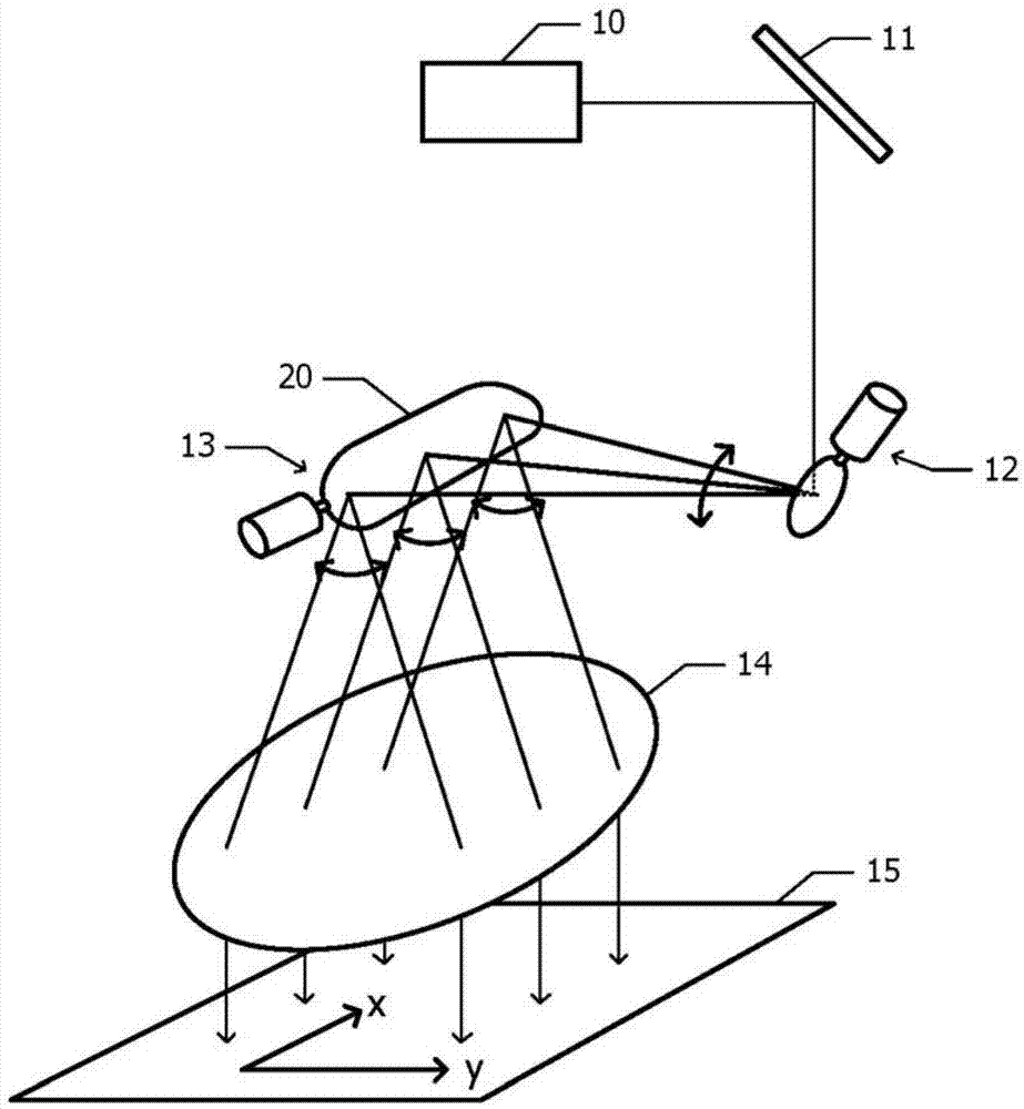
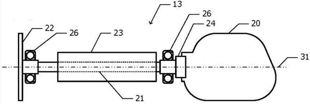
[0026] figure 1 A schematic diagram of laser drilling using the galvano scanner of Example 1 is shown in . The laser beam emitted from the laser light source 10 enters the object 15 through the deflection mirror 11 , the first-stage galvano scanner 12 , the second-stage galvano scanner 13 , and the fθ lens 14 . In addition, beam expanders, masks, lenses, etc. are arranged as necessary. An xy Cartesian coordinate system in which the surface of the object 15 to be processed is defined as an xy plane is defined.

[0027] The first-stage galvano scanner 12 moves the incident point of the laser beam in the x direction on the surface of the object 15 to be processed. When the advancing direction of the laser beam is swung by the first-stage galvano scanner 12 , the incident point of the rotating mirror 20 toward the second-stage galvano scanner 13 moves in the x direction. The second-stage galvano scanner 13 moves the incident point of the laser beam in the y direction on the sur...

Embodiment 2

[0050] Figure 7A and Figure 7B A front view and a rear view of the rotating mirror of the galvano scanner according to the second embodiment are respectively shown in . Hereinafter, differences from the galvano scanner according to the first embodiment described above will be described, and the description of the same configuration will be omitted.

[0051] like Figure 7A As shown, the reflective surface 20A of the rotating mirror 20 of the electronic scanner according to the second embodiment is symmetrical with respect to the rotation center line 31 . like Figure 7B As shown, the first reinforcing rib 41 extends from the grip portion 43 along the rotation center line 31 and becomes thinner toward the tip, as in the case of the first embodiment. The second reinforcing rib 42 branches from the first reinforcing rib 41 as in the case of the first embodiment. Furthermore, the second reinforcing rib 42 extends from a direction perpendicular to the rotation center line 31...


PUM


Abstract

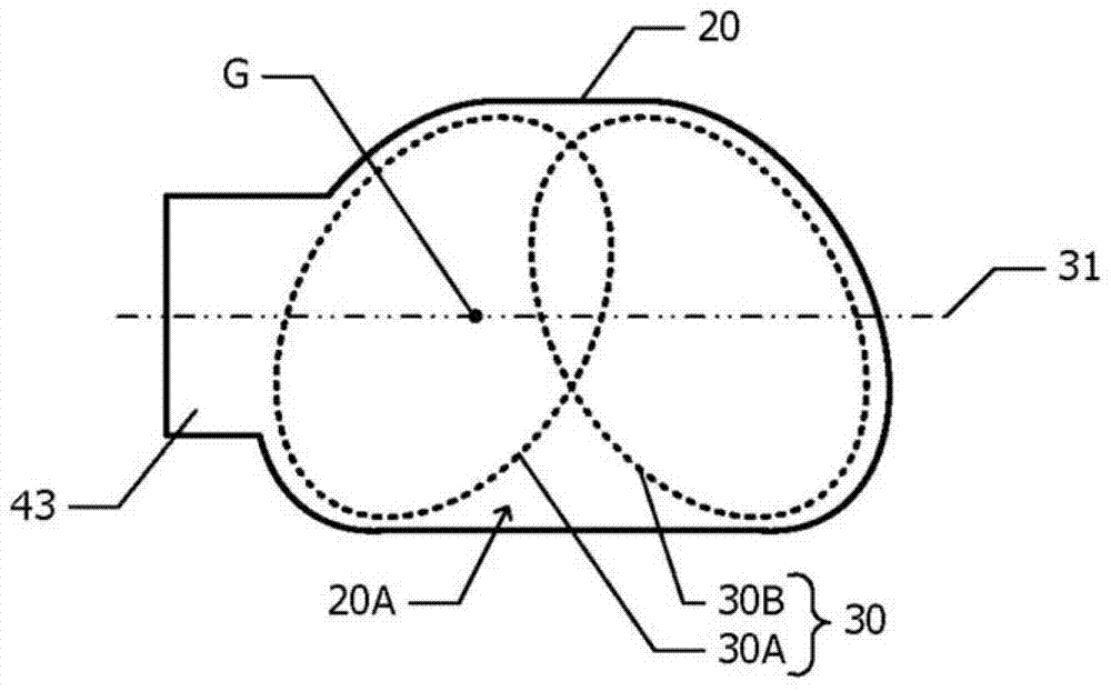
The invention provides a galvano scanner which inhibits response characteristics from deteriorating even if a rotating mirror is bigger in volume. In the galvano scanner provided by the invention, the rotating mirror is installed on the rotating shaft. The rotating mirror has a reflecting surface parallel to the rotating center axis of the rotating shaft. The plane shape of the reflecting surface is not symmetrical relative to the rotating center axis. In an in-plane direction of the reflecting direction, the center of the gravity of the rotating mirror is positioned at a place overlapping with the rotating center axis.

Description

technical field [0001] The present invention relates to a galvanic scanner that reflects a light beam by a rotating mirror that rotates within a predetermined angle range. Background technique [0002] In laser drilling and the like, a galvano scanner is used for scanning a laser beam. A galvano scanner includes a rotating mirror and a motor that rotates the rotating mirror. If the rotating mirror is reciprocally rotated at high speed, the rotating shaft or the rotating mirror is deformed, and a resonance phenomenon occurs. Patent Document 1 discloses a galvano scanner in which the resonance frequency is increased by increasing the rigidity by supporting the rear surface of the rotating mirror with a plate-shaped member. In this galvano scanner, the axis of the rotating shaft passes through the center of gravity of the rotating mirror and the plate member. As a result, resonance due to the asymmetry between the rotating mirror and the plate member is suppressed. [0003]...

Claims


Application Information

Patent Timeline
Patent Type & Authority Patents(China)
IPC IPC(8): G02B26/10
CPCB41J2/471G02B7/182G02B26/105H04N1/113
Inventor 西牧润
Owner SUMITOMO HEAVY IND LTD
Learn More