
Adjusting valve system having energy regeneration effect and energy regeneration method

An energy regeneration and regulating valve technology, applied in the field of regulating valves, can solve the problems of non-action of the actuator, unstable and violent oscillation, etc., and achieve the effect of suppressing excitation, realizing regeneration and utilization, and avoiding the non-action of the actuator.

Active Publication Date: 2019-05-28
SHANDONG UNIV
View PDF4 Cites 2 Cited by
  • Summary
  • Abstract
  • Description
  • Claims
  • Application Information

AI Technical Summary

Problems solved by technology

[0003] The purpose of the present invention is to overcome the deficiencies of the prior art above, to provide a regulating valve system with energy regeneration function, which can effectively reduce the oscillation of the fluid controlled by the regulating valve, and has the function of energy regeneration, which solves the problem of the control valve controlled by the regulating valve. The problem that the actuator does not move easily when the fluid is unstable and violently oscillates

Method used


Image

  • Adjusting valve system having energy regeneration effect and energy regeneration method
  • Adjusting valve system having energy regeneration effect and energy regeneration method
  • Adjusting valve system having energy regeneration effect and energy regeneration method

Examples


Embodiment Construction

[0019] It should be pointed out that the following detailed description is exemplary and intended to provide further explanation to the present application. Unless defined otherwise, all technical and scientific terms used herein have the same meaning as commonly understood by one of ordinary skill in the art to which this application belongs.

[0020] It should be noted that the terminology used here is only for describing specific implementations, and is not intended to limit the exemplary implementations according to the present application. As used herein, unless the context clearly dictates otherwise, the singular is intended to include the plural, and it should also be understood that when the terms "comprising" and / or "comprising" are used in this specification, they mean There are features, steps, operations, means, components and / or combinations thereof.

[0021] For the convenience of description, if the words "up", "down", "left" and "right" appear in the present i...


PUM


Abstract

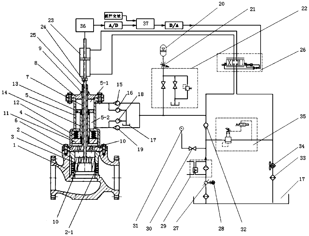
The invention relates to an adjusting valve system having an energy regeneration effect. The system comprises the adjusting valve, an energy regeneration mechanism, and an execution mechanism, whereinthe adjusting valve comprises a valve shell, wherein a flow channel is arranged in the valve shell, and a movable valve core is arranged in the flow channel; the energy regeneration mechanism comprises an energy regeneration cavity body structure connected with the valve shell; the energy regeneration cavity body structure comprises a first cavity body structure and a second cavity body structure; an internal space of the first cavity body structure communicates with the flow channel; a first piston is arranged and is elastically connected with a cavity body wall of the first cavity body structure; a second piston which can do synchronous motion together with the first piston is arranged in the second cavity body structure; two cavity bodies which are divided by the second cavity body structure are connected with an energy storage mechanism and an oil tank through the second piston; the execution mechanism comprises a hydraulic cylinder; and the hydraulic cylinder is connected with avalve core and is also connected with the energy storage mechanism. The adjusting valve system disclosed by the invention has the advantages that energy produced by fluid oscillation can be effectively absorbed and utilized, so that the operation stability of the adjusting valve is improved.

Description

technical field [0001] The invention relates to the technical field of regulating valves, in particular to a regulating valve system and method with capacity regeneration function. Background technique [0002] Control valves are widely used in various fluid control occasions. The inventors have found that under extreme working conditions, when the fluid controlled by the regulating valve oscillates violently, the spool of the regulating valve is likely to bear sudden additional loads. The fluid control on the ship is also inseparable from the regulating valve. Ship control valves play a key role in ensuring the normal fluid delivery of ship power systems. Practice has proved that the environment of the ship is complex and changeable. With the change of various working conditions, the sudden additional load borne by the control valve may greatly exceed the rated load, resulting in the failure of the actuator of the valve, reducing the control accuracy and endangering the s...

Claims


Application Information

Patent Timeline
Patent Type & Authority Applications(China)
IPC IPC(8): F16K31/122F16K3/24F16K37/00F16K47/00F15B1/02
CPCY02E60/16
Inventor 谢玉东李传栋王勇陈晨韩家桢吕凯
Owner SHANDONG UNIV
Learn More