Rotation angle detection device and rotation angle detection method
- Summary
- Abstract
- Description
- Claims
- Application Information
AI Technical Summary
Benefits of technology
Problems solved by technology
Method used
Image
Examples
first embodiment
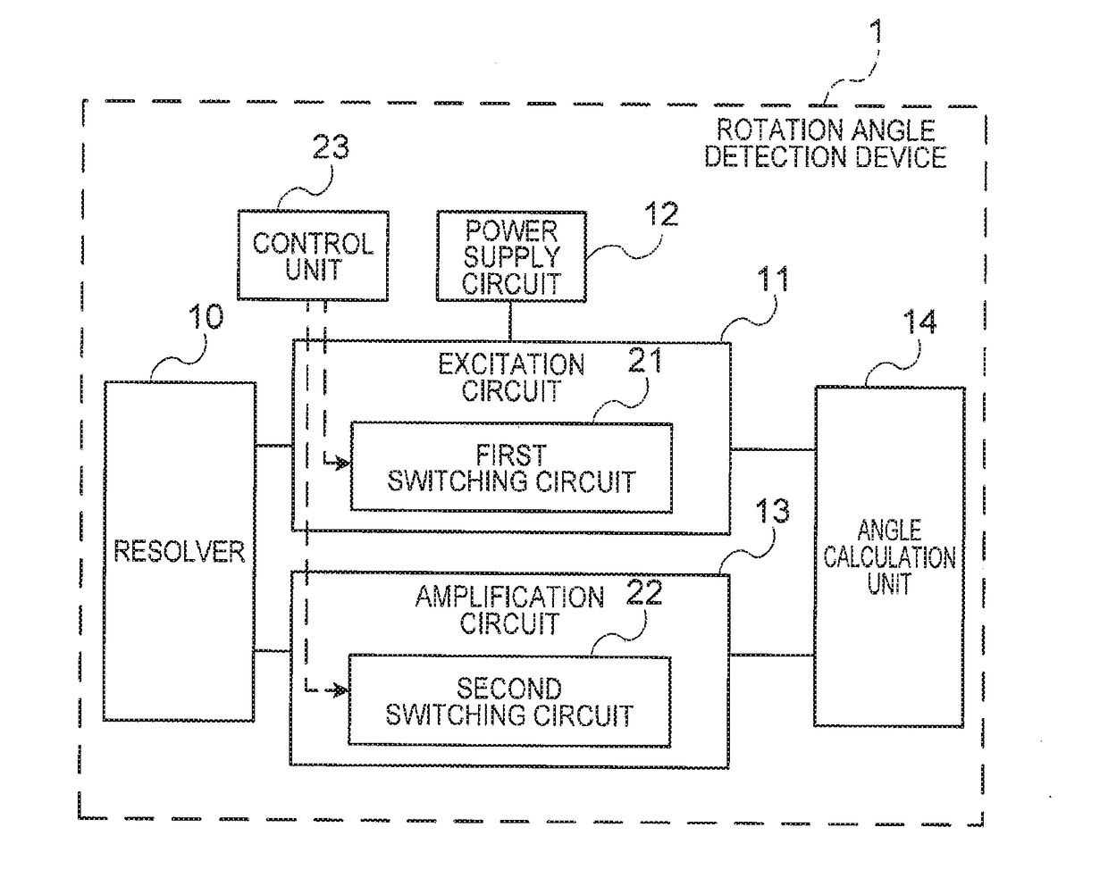
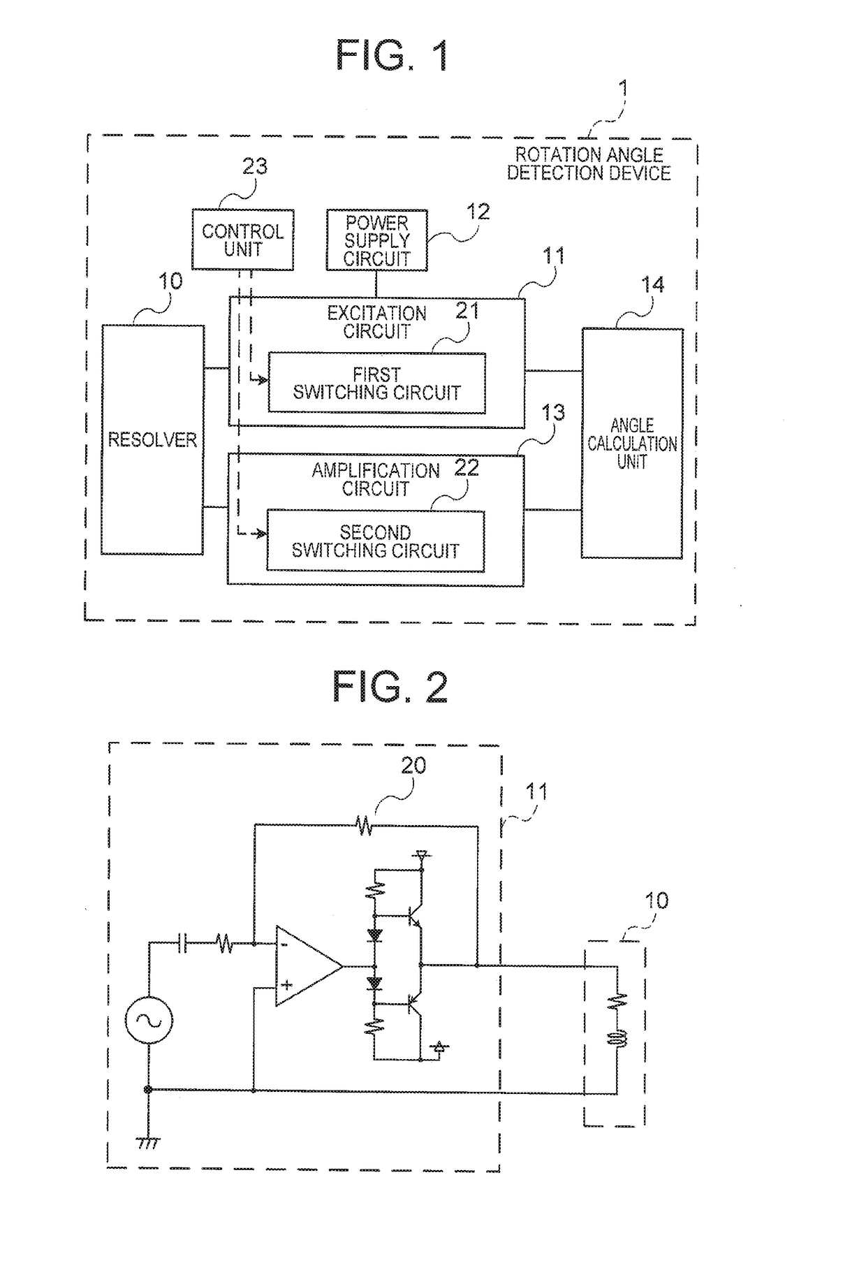
[0018]FIG. 1 is a block drawing showing the configuration of a rotation angle detection device 1 according to a first embodiment of the present invention. The rotation angle detection device 1 of the first embodiment comprises a resolver 10, an excitation circuit 11, a power supply circuit 12, an amplification circuit 13, an angle calculation unit 14, a first switching circuit 21, a second switching circuit 22, and a control unit 23.
[0019]Furthermore, FIG. 2 is a circuit diagram illustrating one example of the excitation circuit 11 in the rotation angle detection device 1 according to the first embodiment of the present invention. Below, the constituent elements and functions of the rotation angle detection device 1 according to the first embodiment will be described with reference to FIG. 1 and FIG. 2.
[0020]The resolver 10 has an excitation coil and an induction coil. A magnetic field produced by an excitation signal applied to the excitation coil of the resolver 10 is frequency-mo...
second embodiment
[0042]The first embodiment above describes a method which increases the amplitude of the excitation signal to improve the detection accuracy of the resolver 10 by providing the first switching circuit 21 in the excitation circuit 11 and switching the feedback resistance 20 of the operating amplifier of the excitation circuit 11. Meanwhile, the second embodiment describes a method in which the amplitude of the excitation signal is raised in accordance with the output voltage of the power supply circuit 12 to improve the detection accuracy of the resolver 10, by providing the first switching circuit 21 in the power supply circuit 12 and switching the output voltage of the power supply circuit 12.
[0043]FIG. 4 is a block drawing showing the configuration of the rotation angle detection device 2 according to the second embodiment of the present invention. FIG. 4 differs from FIG. 1 relating to the first embodiment in that the first switching circuit 21 is provided inside the power supply...
third embodiment
[0052]The first embodiment above describes a method which raises the amplitude of the excitation signal to improve the detection accuracy of the resolver 10 by switching the feedback resistance 20 of the operating amplifier of the excitation circuit 11. Meanwhile, a third embodiment of the present invention describes a method which raises the frequency of the excitation signal to improve the detection accuracy of the resolver 10, by switching the resistance of the excitation circuit 11 which sets the transmission frequency of the excitation signal.
[0053]A block diagram illustrating the configuration of the rotation angle detection device 1 according to the third embodiment of the present invention is the same as FIG. 1 relating to the first embodiment described above. However, the third embodiment differs from the first embodiment described above in that the first switching circuit 21 switches the frequency of the excitation signal, rather than the size of the excitation signal. The...
PUM
 Abstract
Description
Claims
Application Information
 - R&D
- Intellectual Property
- Life Sciences
- Materials
- Tech Scout
- Unparalleled Data Quality
- Higher Quality Content
- 60% Fewer Hallucinations
Browse by: Latest US Patents, China's latest patents, Technical Efficacy Thesaurus, Application Domain, Technology Topic, Popular Technical Reports.
© 2025 PatSnap. All rights reserved.Legal|Privacy policy|Modern Slavery Act Transparency Statement|Sitemap|About US| Contact US: help@patsnap.com


