Unlock instant, AI-driven research and patent intelligence for your innovation.

Developing device and image forming device

A developing device and developer technology, applied in the fields of developing devices and image forming devices, can solve the problems of image contamination, carrier scattering, insufficient toner peeling, etc.

Inactive Publication Date: 2016-04-27
KYOCERA DOCUMENT SOLUTIONS INC
View PDF5 Cites 0 Cited by
  • Summary
  • Abstract
  • Description
  • Claims
  • Application Information

AI Technical Summary

Problems solved by technology

If the length of the magnetic brush is too long relative to the length of the toner holding rotating body, the carrier is likely to fly from the end in the longitudinal direction of the magnetic brush to the inside of the frame, and it is easy to be formed of a conductive material for biasing. The flange portion of the toner retaining rotor leaks the bias voltage applied between the toner retaining rotor and the developer retaining rotor
[0007] On the contrary, if the length of the magnetic brush is too short relative to the length of the toner holding rotating body, the residual toner will not be sufficiently peeled off by the magnetic brush, and the toner will remain on the surface of the toner holding rotating body and Deteriorated toner tends to scatter around or cause contamination at the edge of the image
[0008] In addition, if the length of the magnetic brush is too short relative to the length of the toner holding rotating body, gaps will be formed at both ends of the toner holding rotating body in the longitudinal direction, and the material inside the developing device that is stirred by the stirring roller Toner or carrier is easily scattered through this gap

Method used


Image

  • Developing device and image forming device
  • Developing device and image forming device
  • Developing device and image forming device

Examples


Embodiment Construction

[0023] Hereinafter, embodiments of the present invention will be described with reference to the drawings.

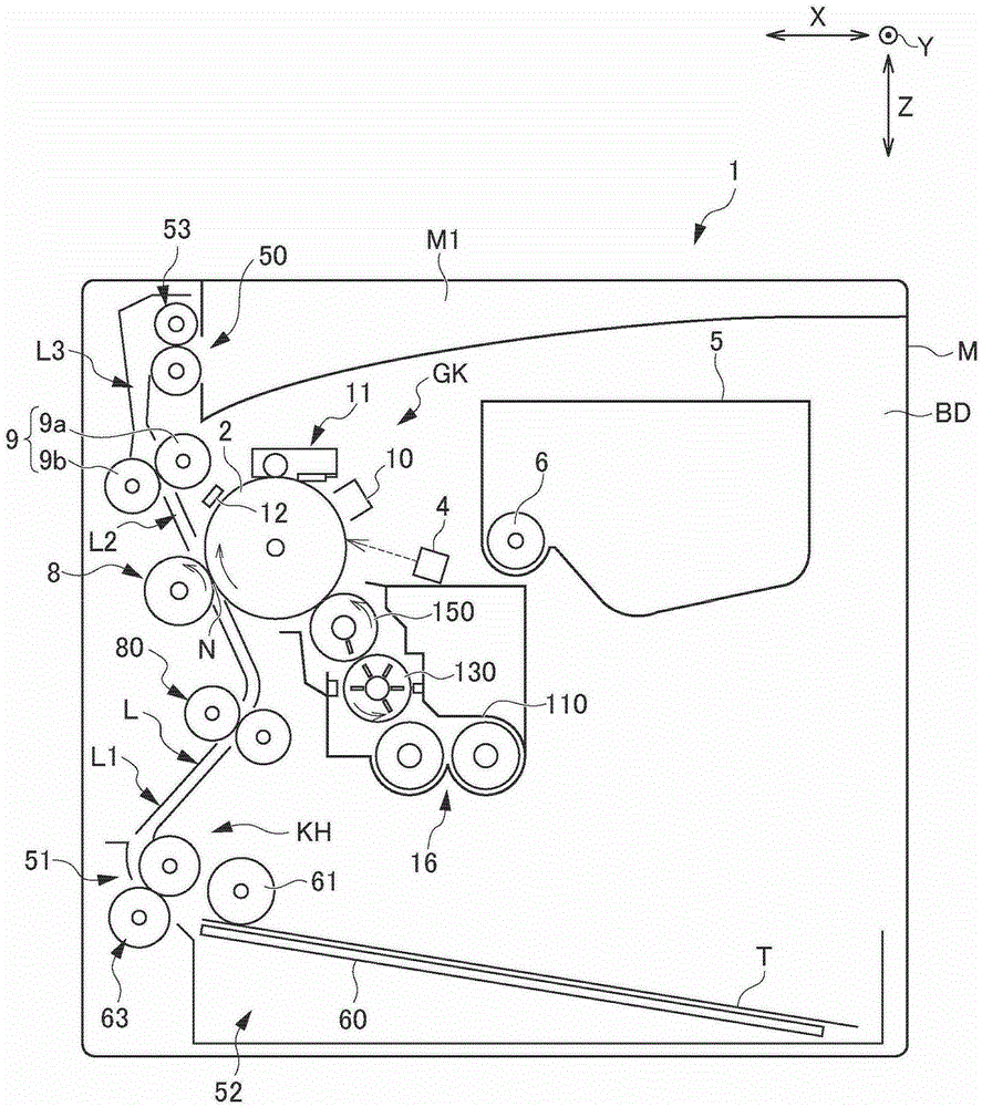
[0024] pass figure 1 The overall structure of the printer 1 as the image forming apparatus in the embodiment of the present invention will be described. figure 1 It is a diagram for explaining the arrangement of each component of the printer 1 according to the embodiment of the present invention.

[0025] In the following description, when the user stands on the front side of the printer 1 and looks at it, the left-right direction is referred to as the X direction, the front-back (depth) direction is referred to as the Y direction, and the up-down direction (vertical direction) is referred to as the Z direction.

[0026] like figure 1 As shown, the printer 1 as an image forming apparatus includes an apparatus main body M, an image forming unit GK, and a paper feeding and discharging unit KH. The image forming unit GK forms a predetermined toner image on a sheet of pa...


PUM


Abstract

A longitudinal end portion of an opposing magnetic member of a developer supporting rotator is positioned more longitudinally outside than a longitudinal end portion of a toner supporting side magnetic member. With respect to the opposing magnetic member facing the toner supporting side magnetic member and a downstream magnetic member disposed more downstream than the opposing magnetic member in a rotational direction, a magnetic force generated in a vicinity of both longitudinally end portions thereof is greater than a magnetic force generated longitudinally inside thereof. A housing includes a sealing portion that projects from a position facing a face at a longitudinal end portion of the developer supporting rotator toward the face, such that the sealing portion prevents the toner in a space between the face and an inner face of the housing from scattering outside.

Description

technical field [0001] The present invention relates to a developing device for developing an electrostatic latent image formed by electrophotography, and an image forming device having the developing device. Background technique [0002] In recent years, a so-called touchdown system (also referred to as a hybrid system) developing device has been known. In this method, a two-component developer including at least a carrier and a toner is held on the surface of a developer holding rotating body, and a magnetic brush is formed from the carrier. The toner supplied from the magnetic brush to the toner holding rotary forms a toner layer on the surface of the toner holding rotary, and the toner is caused to fly from the toner layer onto the image holding body. Thereby, the electrostatic latent image on the surface of the image holder is developed as a toner image. [0003] In the falling type developing device, the toner in the toner layer formed on the surface of the toner hol...

Claims


Application Information

Patent Timeline
Patent Type & Authority Patents(China)
IPC IPC(8): G03G15/09G03G15/00
CPCG03G15/0921G03G15/0935G03G15/095
Inventor 滨川博幸
Owner KYOCERA DOCUMENT SOLUTIONS INC