Method for identifying cascading failure of power system

A power system and cascading failure technology, applied in the direction of electrical components, circuit devices, AC network circuits, etc.

Active Publication Date: 2013-09-18
湖南世优电力科技股份有限公司
View PDF4 Cites 9 Cited by
  • Summary
  • Abstract
  • Description
  • Claims
  • Application Information

AI Technical Summary

Problems solved by technology

The chain trip stage of the transmission line of the system is mostly accompanied by the removal of loads and generator sets, and the resulting frequency deviation and generator speed regulation process cannot be ignored

Method used


Image

  • Method for identifying cascading failure of power system
  • Method for identifying cascading failure of power system
  • Method for identifying cascading failure of power system

Examples


Embodiment 1

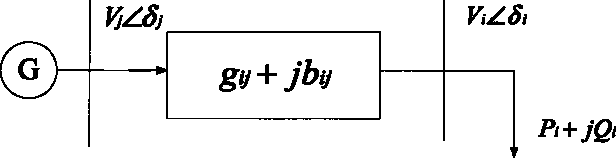
[0051] Such as figure 1 Shown is the geographical wiring diagram of the two-node system. This is to illustrate the voltage stability index VSI and the voltage critical value V of the power system by taking the two-node system as an example. th derivation process. symbol in the figure represents the generator, the vertical solid line represents the transmission bus, |g ij +jb ij | indicates the impedance of the transmission line, and the arrow indicates the load.

[0052] (1) For any two-node power system:

[0053] S i * = Y ii ‾ V i 2 + V ‾ * j V j ‾ Y ij ‾ ...

Embodiment 2

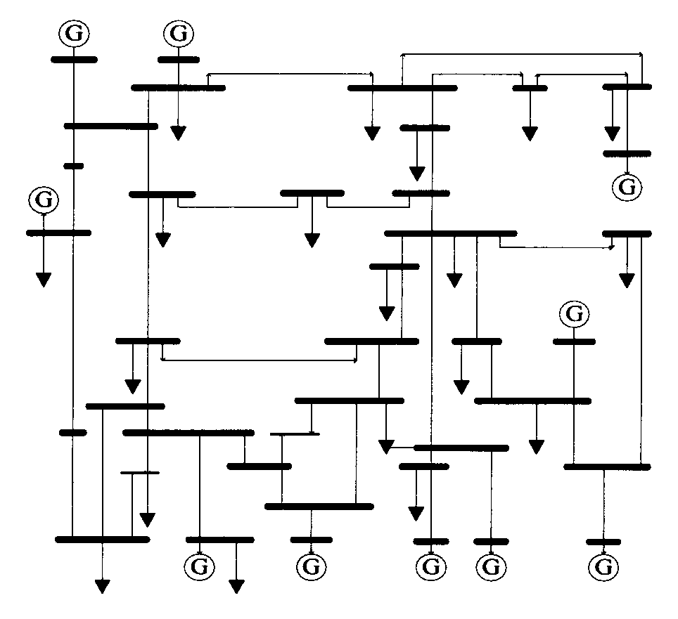
[0089] Such as figure 2 Shown is the geographic wiring diagram of IEEE-39 node system, which is used as the research standard power grid of the present invention, including 10 generators and 34 transmission lines. symbol in the figure Indicates the generator, the thin solid line indicates the transmission line, the thick solid line indicates the node bus, and the arrow indicates the load.

[0090] The inventive method is described in detail below:

[0091] (1) Basic parameter setting: load characteristic parameter k i = 1.5, a i =0.85,b i =0.1,c i =0.05, k' i = 1.5, a' i =0.8, b' i =0.15, c' i =0.05, generator speed regulation parameter: K G =20,K D = 1.5. The basic Newton method is used to calculate the power flow of the system; the partial power flow distribution of the IEEE-39 node system is shown in the table below, and the benchmark value is 1000MW:

[0092] node number

node voltage

Node injected power

1

0.982

(0.663008934734...

Embodiment 3

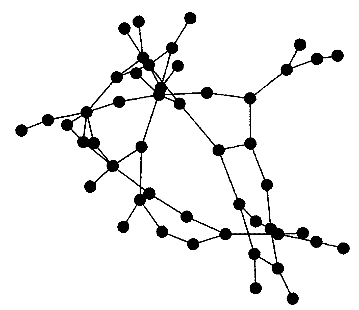
[0119] Such as image 3 Shown is a topological structure diagram of the 500kv side of a power grid in Guangdong, which is used as the actual power grid studied by the present invention. Nodes in the figure represent buses and substations, and thin lines represent transmission lines.

[0120] The inventive method is described in detail below:

[0121] (1) Basic parameter setting: load characteristic parameter k i = 1.5, a i =0.85,b i =0.1,c i =0.05, k' i = 1.5, a' i =0.8, b' i =0.15, c' i =0.05, generator speed regulation parameter: K G =20,K D = 1.5, using the basic Newton method to calculate the system power flow as shown in Table 3;

[0122] node number

Node voltage p.u

Node injection power (1000MW)

1

1.006

(27.2326710998-30.0611882767j)

2

1.053763

(-19.931-1.272j)

3

1.019433

(15.716+1.154j)

4

1.042896

(-9.739+0.788j)

5

1.068123

(-24.554+4.374j)

6

1.055256

-0...


PUM


Abstract

The invention discloses a method for identifying the cascading failure of a power system. Considering the speed governing and load response of a power generator, a more practical power system load flow calculation model is established, and the method overcomes the impact that a traditional load flow calculation model cannot reflect the regulation action and load response of the power generator in the load flow calculation model. From the perspective of the operation status of the system, the method analyzes the relationship between stable voltage and the failure in the cascading failure; and deducts the stable indicator of the system voltage and the critical value of the indicator by analyzing the change of a Jacobi matrix element value in order to quantitatively analyze the relationship between the critical value of the voltage and the operation status of the system. As the load is increased, the system has higher risk of the cascading failure. During the process, the stable indicator of the system voltage is gradually reduced, and the critical value is always maintained at 0.5 (+ / -0.03). In an actual system, the critical value of the voltage which is calculated remains unchanged in the cascading failure, 0.6 is selected as the critical value of voltage collapse in a power grid in the actual system, so as to identify whether the power grid faces the risk of large-scale power-off or not. In such a manner, the method has better actual guiding significance.

Description

technical field [0001] The invention belongs to the technical field of power systems and automation thereof, and provides a method for identifying cascading failures in power systems. Background technique [0002] The research on blackouts in power systems at home and abroad shows that catastrophic accidents in modern power grids caused by chain reactions of faults are manifested as chain reaction trips of a series of components. The possibility of cascading failures is very small, but it will cause serious consequences to the safety of the power grid, which has attracted great attention from scholars at home and abroad. In-depth research on cascading faults in power grids is of great significance for power grid planning, power grid operation decision-making, and ensuring safe and stable operation of power grids. [0003] The research on grid cascading failures is mainly carried out from the following aspects: 1) Apply the self-organized criticality theory in physics to the...

Claims


Application Information

Patent Timeline
Patent Type & Authority Applications(China)
IPC IPC(8): H02J3/00G06Q50/06
Inventor 曹一家蔡晔谭玉东辛拓杨银国林建熙李帅虎吴卫良李勇
Owner 湖南世优电力科技股份有限公司
Why Eureka
Try Eureka