Telescopic shaft

一种伸缩轴、螺纹轴的技术,应用在伸缩轴领域,能够解决耐久性问题等问题,达到提高耐久性、减少和变形、顺畅润滑的效果

Inactive Publication Date: 2013-09-18
NSK LTD
View PDF7 Cites 12 Cited by
  • Summary
  • Abstract
  • Description
  • Claims
  • Application Information

AI Technical Summary

Problems solved by technology

However, since the telescopic shaft in Patent Document 2 generates a large surface pressure locally, there is a problem in terms of durability.

Method used


Image

  • Telescopic shaft
  • Telescopic shaft
  • Telescopic shaft

Examples


Embodiment 1

[0049] Below, refer to Figure 1 ~ Figure 4 Example 1 of the present invention will be described.

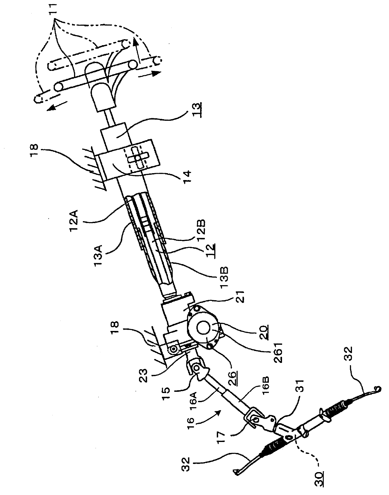
[0050] like figure 1 As shown, the steering device of an embodiment of the present invention has: figure 1 The right side in the middle) the steering shaft 12 of the steering wheel 11 is installed; the steering column 13 through which the steering shaft 12 is inserted; Body front side ( figure 1 The left side in ) the steering gear 30 connected via a rack and pinion structure not shown.

[0051] The steering shaft 12 has an outer shaft 12A and an inner shaft 12B. The outer shaft 12A and the inner shaft 12B are combined so that torque can be freely transmitted and relative displacement in the axial direction is possible. That is, a plurality of externally threaded splines are formed on the outer periphery of the inner shaft 12B on the vehicle body rear side. On the inner periphery of the outer shaft 12A on the vehicle body front side, a plurality of female splines are forme...

Embodiment 2

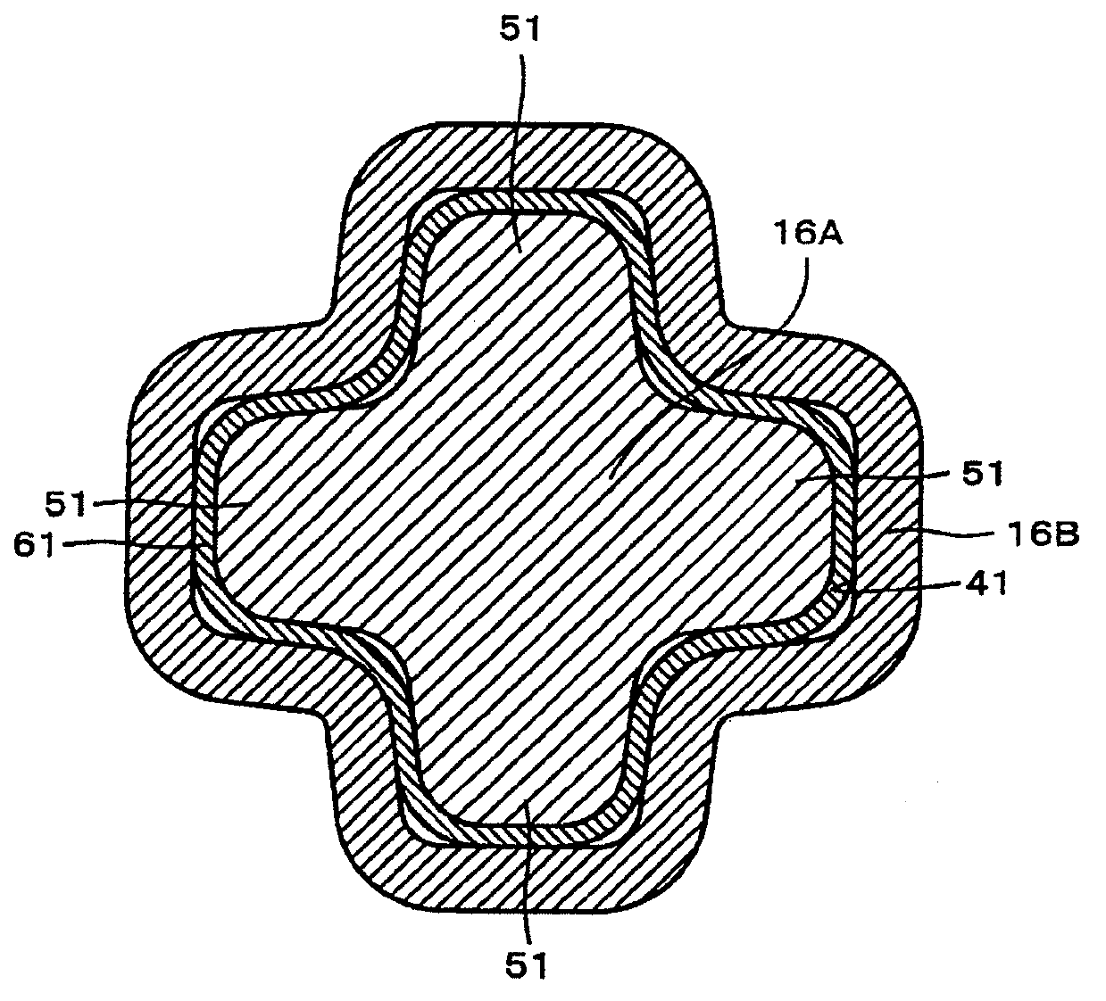
[0070] Next, refer to Figure 6 Example 2 of the present invention will be described. Hereinafter, features different from those of Embodiment 1 will be mainly described, and redundant descriptions will be omitted. Example 2 is an example in which a relief portion is formed at the dedendum of the covering portion 61 of the protruding tooth 51 .

[0071] like Figure 6 As shown, the telescopic shaft of the second embodiment is the same as that of the first embodiment, and the tooth surface 511 of the protruding tooth 51 of the externally threaded shaft 16A is covered with the covering part 61 . The tooth surface 611 of the covering portion 61 of the protruding tooth 51 protrudes in an arc shape outward in the radial direction of the male thread shaft 16A. The curvature radius R1 of the tooth surface 611 is smaller than the curvature radius R2 of the tooth surface 411 of the tooth groove 41 . In addition, R chamfers (chamfers) 612 and 613 protruding outward in the radial dir...


PUM


Abstract

A telescopic shaft is provided with a male shaft having an outer periphery on which a plurality of protruding teeth are formed, and with a female shaft having an inner periphery on which a plurality of tooth grooves are formed. The male shaft and the female shaft are slidable relative to each other in the axial direction, and the tooth grooves of the female shaft are externally fitted to the protruding teeth of the male shaft in such a way that rotational torque can be transferred between the male shaft and the female shaft. One of the curvature radii of the tooth faces of the protruding teeth and one of the curvature radii of the tooth faces of the tooth grooves are smaller than the other curvature radii of the tooth faces of the protruding teeth and the other curvature radii of the tooth faces of the tooth grooves.

Description

technical field [0001] The invention relates to a telescopic shaft, in particular to a telescopic shaft with an externally threaded shaft and an internally threaded shaft capable of transmitting torque and sliding relative to each other along the axial direction. Background technique [0002] The steering device has telescopic shafts such as intermediate shafts and steering shafts, and these have externally threaded shafts and internally threaded shafts that can transmit torque and are connected in a relatively slidable manner in the axial direction. The intermediate shaft needs to have a telescoping function for fitting and connecting with the wheel shaft after being temporarily contracted when fixing the universal joint to the wheel shaft meshing with the rack shaft of the steering gear, or for absorbing the gap between the wheel shaft and the vehicle body frame. relative displacement between them. [0003] In order to transmit the steering force of the steering wheel to ...

Claims


Application Information

Patent Timeline
Patent Type & Authority Applications(China)
IPC IPC(8): F16D3/06B62D1/20
CPCB62D1/16B62D1/20F16C3/035F16C2326/24F16D3/06F16D2001/103
Inventor 黑川祥史
Owner NSK LTD
Why Eureka
Try Eureka