Mechanism and method for automatically cleaning cutting wheel

A technology for automatic cleaning and cutting knives, applied in cleaning methods and utensils, cleaning methods using tools, cleaning methods using liquids, etc., can solve problems affecting equipment output, save cleaning manpower and working hours, reduce The impact of the upstream film supply line and the effect of improving production efficiency

Inactive Publication Date: 2013-09-25
EVERDISPLAY OPTRONICS (SHANGHAI) CO LTD
View PDF10 Cites 4 Cited by
  • Summary
  • Abstract
  • Description
  • Claims
  • Application Information

AI Technical Summary

Problems solved by technology

This process affects the throughput of the equipment and must be manually intervened

Method used


Image

  • Mechanism and method for automatically cleaning cutting wheel
  • Mechanism and method for automatically cleaning cutting wheel
  • Mechanism and method for automatically cleaning cutting wheel

Examples


no. 1 example

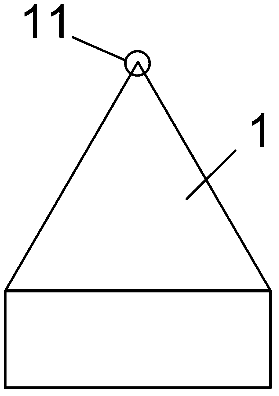
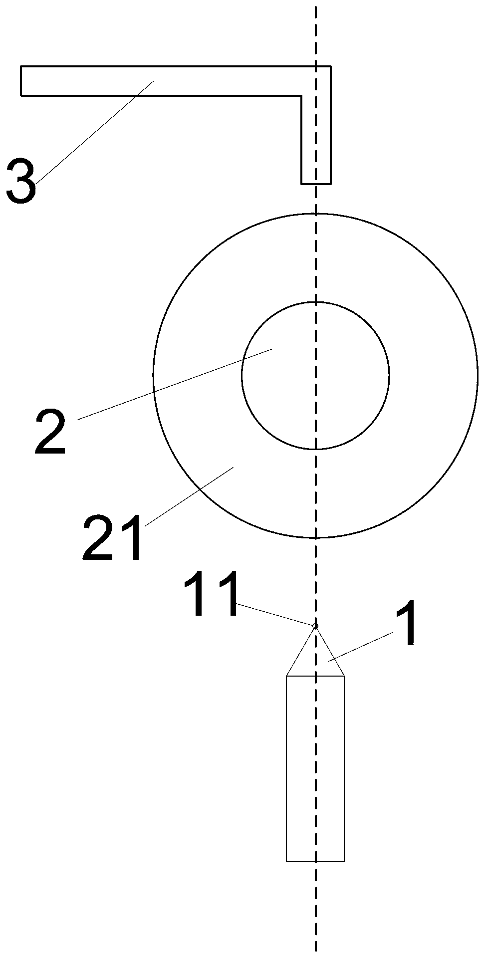
[0060] image 3 According to the first embodiment of the present invention, a schematic structural diagram of the automatic cleaning mechanism of the cutting wheel of the present invention is shown. Such as image 3 As shown, the cutting wheel automatic cleaning mechanism of the present invention is used to clean the cutting wheel 11 on the cutting knife 1, including: cleaning roller 2, lifting device (not shown in the figure), motor (not shown in the figure) and cleaning dropper 3 .

[0061] The cleaning roller 2 is arranged above the cutter wheel 11 . The cleaning roller 2 comprises a layer of cleaning medium 21 . The cleaning medium 21 is coated on the outer surface of the cleaning roller 2 . The material of the cleaning medium 21 is a porous absorbent body. In this embodiment, the material of the cleaning medium 21 is sponge, but it is not limited thereto.

[0062] The lifting device drives the cleaning roller 2 to contact or leave the cutter wheel 11 . The lifting ...

no. 2 example

[0071] A glass cutting device of the present invention is to combine the cutting wheel automatic cleaning mechanism in the first embodiment into the glass cutting production line equipment, which includes at least one cutting wheel, at least one conveying device for transporting glass plates, and the above-mentioned Cutting knife wheel automatic cleaning mechanism. The cutting knife wheel automatic cleaning mechanism is used to clean the cutting knife wheel on the cutting knife, including: cleaning roller, lifting device, motor and cleaning liquid drop tube.

[0072] The cleaning roller is arranged above the cutter wheel. Cleaning rollers consist of a layer of cleaning media. The cleaning medium is coated on the outer surface of the cleaning roller. The material of the cleaning medium is a porous absorbent body. In this embodiment, the material of the cleaning medium is sponge, but not limited thereto.

[0073] The lifting device drives the cleaning roller to contact or le...


PUM


Abstract

The invention provides a mechanism and a method for automatically cleaning a cutting wheel. The mechanism comprises a cleaning roller, a lifting device, a motor and a cleaning fluid drip tube; the cleaning roller comprises at least one layer of cleaning media; the lifting device drives the cleaning roller to be in contact with the cutting wheel or to be separated from the cutting wheel; the motor drives the cleaning roller to rotate; the cleaning fluid drip tube is arranged above the cleaning roller and regularly drips cleaning fluid to the cleaning roller. The method includes that the cleaning roller descends, is in contact with the cutting wheel and rotates, and the cleaning media clean the surface of the cutting wheel; the cleaning roller ascends and is reset. The mechanism and the method for automatically cleaning the cutting wheel have the advantages that grooves of the cutting wheel can be regularly cleaned by the aid of an automatic roller mechanism, manual cleaning operation is replaced, and cleaning operation is executed under the regular and quantitative control, so that the cleanness of the cutting wheel can be kept, cleaning labor and working hours can be saved, influence on an upstream sheet supply production line is greatly reduced, and the production efficiency is improved.

Description

technical field [0001] The invention relates to a cutter wheel cleaning mechanism, in particular to a mechanism and method for automatically cleaning a glass cutting cutter wheel. Background technique [0002] In the production process of the display panel, glass cutting is an essential process, and the raw glass plate is divided into the required glass panel size according to the cutting line. [0003] figure 1 A structural schematic diagram of a cutting knife in the prior art is shown. Such as figure 1 As shown, it is a cutting knife 1 in the prior art, and a high-speed rotating cutting wheel 11 is provided on the end of the cutting knife 1 in contact with the glass panel. Usually the diameter of the cutter wheel 11 is very small, generally less than or equal to 0.3 cm. [0004] figure 2 A schematic diagram showing the surface of a cutting wheel in a prior art cutting knife. Such as figure 2 As shown, there are many gear teeth distributed in the cutting direction ...

Claims


Application Information

Patent Timeline
Patent Type & Authority Applications(China)
IPC IPC(8): B08B7/04B08B1/04B08B3/08
CPCY02P40/57
Inventor 李政军
Owner EVERDISPLAY OPTRONICS (SHANGHAI) CO LTD
Why Eureka
Try Eureka