Blade belt cutting device

A cutting device and blade technology, applied in the direction of feeding device, positioning device, storage device, etc., can solve the problems of low work efficiency, inconvenient operation, frequent shutdown, etc.

Inactive Publication Date: 2013-09-25
苏州快吉刀片制造有限公司
View PDF7 Cites 6 Cited by
  • Summary
  • Abstract
  • Description
  • Claims
  • Application Information

AI Technical Summary

Problems solved by technology

[0002] In the production of metal blades, the cutting of the general blade is completed by the sharp edge of the mold. The cutting device currently used is interval cutting, that is, the cutting blade stops running after being transported to the rated lengt

Method used


Image

  • Blade belt cutting device
  • Blade belt cutting device

Examples


Embodiment Construction

[0017] The specific implementation manners of the present invention will be further described in detail below in conjunction with the accompanying drawings and embodiments. The following examples are used to illustrate the present invention, but are not intended to limit the scope of the present invention.

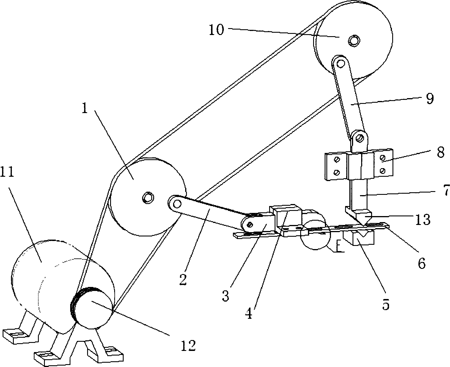
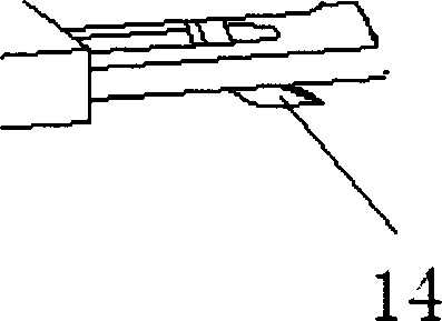
[0018] refer to Figure 1~2 , the slider crank transmission mechanism includes: a frame, a first fixed assembly 4, a first crank wheel 1, a first connecting rod 2 and a first slider 3 connected in sequence, and the end of the first slider 3 is lower A ratchet 14 is provided on the side, and the first slider 3 is horizontally positioned on the frame through the first fixing assembly 4 .

[0019] The slider crank punching mechanism includes: a frame, a second fixed assembly 8, a second crank wheel 10 connected in sequence, a second connecting rod 9 and a second slider 7, the end of the second slider 7 A punch 13 is provided, and the second slider 7 is vertically positioned...


PUM


Abstract

The invention relates to the field of blade producing and processing and discloses a blade belt cutting device which comprises a rack, a motor, a crank-slider transmission mechanism used for pushing a blade belt, and a crank-slider blanking mechanism used for cutting the blade belt. A belt wheel of the motor is in belt connection with a first crank wheel and a second crank wheel. By the blade belt cutting device, conveying and cutting of a blade can be performed synchronously.

Description

technical field [0001] The invention relates to the field of blade production and processing, in particular to a blade band cutting device. Background technique [0002] In the production of metal blades, the cutting of the general blade is completed by the sharp edge of the mold. The cutting device currently used is interval cutting, that is, the cutting blade stops running after being transported to the rated length, and the cutting operation is carried out by a fixed cutting mechanism. Since the conveying and cutting of the blades cannot be carried out synchronously, there are disadvantages such as frequent shutdown, inconvenient operation, and low work efficiency. Contents of the invention [0003] (1) Technical problems to be solved [0004] The technical problem to be solved by the present invention is to provide a cutting device for blade bands, so that the feeding and cutting of the blades can be carried out synchronously. [0005] (2) Technical solution [0006...

Claims


Application Information

Patent Timeline
IPC IPC(8): B21D43/04B21D28/02
Inventor 张东荣
Owner 苏州快吉刀片制造有限公司
Why Eureka
Try Eureka