Continuous casting billet chatter mark control method

A control method and continuous casting billet technology, applied in the field of metal continuous casting, can solve the problems of weakening the meniscus, failure to control vibration marks, adverse effects on production efficiency, etc., to improve surface quality, eliminate vibration marks, and achieve maintenance-free The effect of post-grinding processing

Active Publication Date: 2013-09-25
BAOSHAN IRON & STEEL CO LTD
View PDF8 Cites 6 Cited by
  • Summary
  • Abstract
  • Description
  • Claims
  • Application Information

AI Technical Summary

Problems solved by technology

However, this technology needs to modify the existing continuous casting mold and add auxiliary heaters, so it is difficult to implement under the existing continuous casting conditions
Chinese patent 200710137257.1 discloses a two-stage continuous casting mold. The meniscus of the mold is made of a material with high temperature resistance and low thermal conductivity to weaken the cooling of the metal meniscus (actually equivalent to the increase of the meniscus of the mold. Hot top), because the initial solidification point of the metal moves down, and even the meniscus metal does not solidify at all, thus weakening the formation of vibration marks. There are still major problems in the crystallizer production of this technology. The weak cold of the meniscus metal causes the entire The reduction of continuous casting cooling intensity will have a negative impact on production efficiency, and the weakening of the solidification of the billet shell in the mold will also increase the risk of steel breakout
Foreign patents JP2006247722A, JP58141832A and JP2006061946A etc. disclose a method of coating on the surface of the crystallizer to improve the wear resistance of the crystallizer or prevent scaling on the inner wall of the crystallizer. The coatings used are generally Ni-based or other alloy coatings, and the thermal conductivity of the coatings Generally, the thermal conductivity is lower than that of the mold copper material. Objectively speaking, the increase of the coating can partially weaken the heat transfer of the meniscus and reduce the vibration marks, but in fact the main purpose of these coatings is to increase the wear resistance of the mold or improve crystallization. The attachments on the water tank on the inner wall of the crystallizer are not a control technology for vibration marks, and these are all coated on the entire length of the crystallizer, which cannot meet the requirements for controlling vibration marks at all.

Method used


Image

  • Continuous casting billet chatter mark control method
  • Continuous casting billet chatter mark control method

Examples


Embodiment 1

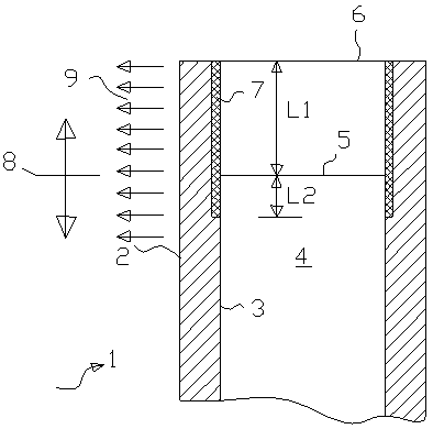
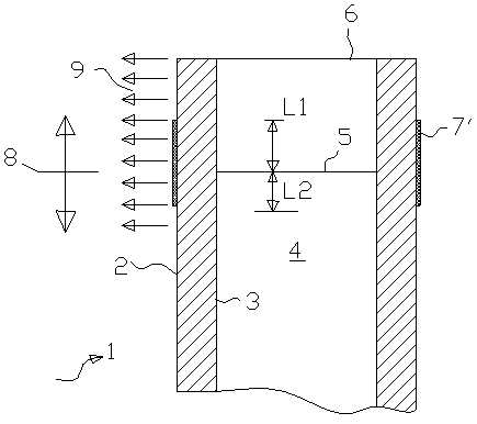
[0023] The heat insulation material used for the heat insulation layers 7, 7' in Embodiment 1 and Embodiment 2 is ceramics or plastics, or metals or alloys with low thermal conductivity.

[0024] As shown in table 1, the continuous casting crystallizer designed according to the continuous casting slab vibration mark control method of the present invention, the total thermal resistance at its meniscus place and the contrast of the total thermal resistance of the traditional continuous casting crystallizer meniscus Data, wherein A shows the thermal resistance parameter of traditional continuous casting crystallizer, and its total thermal resistance is defined as percentage 100, and B, C, D are the change situation of the crystallizer total thermal resistance that different insulation layers 7 of the present invention cause , all the insulation layers 7 are plated on the inner wall of the crystallizer, and the materials of different insulation layers 7 are different, the thermal c...


PUM


Abstract

The invention belongs to the technical field of continuous casting of metal, and relates to a continuous casting crystallizer casting blank chatter mark control method. The continuous casting billet chatter mark control method is characterized in that molten metal pouring is performed on a continuous casting crystallizer meniscus area and the position above thereof, and a heat insulation material is additionally arranged on the inner wall or the outer wall of the crystallizer so as to reduce heat exchange flowing at the meniscus area and the position above thereof, thereby weakening the initial solidification of the molten metal at the meniscus. The meniscus area and the position above thereof subjected to the molten metal pouring is the area that is the sum of the two lengths which respectively are the distance between a position 30-50 mm below a molten metal top surface of the crystallizer and an upper opening of the crystallizer and the distance between the molten metal top surface and the upper opening of the crystallizer. According to the method provided by the invention, chatter marks on the surface of a casting blank can be reduced or eliminated, so that the surface quality of the casting blank can be improved and the casting blank can be free from support processing of grinding.

Description

technical field [0001] The invention belongs to the technical field of metal continuous casting, and relates to a method for controlling vibration marks of a continuous casting crystallizer. Background technique [0002] A landmark technology in the development of modern continuous casting technology is the use of mold vibration technology, and the periodic vibration of the mold also has a periodic impact on the initial solidification of the slab, thus forming equidistant distribution on the surface of the slab, and Vibration marks with a certain depth. Because vibration marks are common in continuous casting production, vibration marks were often not regarded as quality defects in the early stage. more and more important. The latest research shows that the vibration mark is actually a quality defect of the slab, which is the source of defects such as transverse cracks, air bubbles, and slag inclusions on the surface of the continuous casting slab. The existence of vibrat...

Claims


Application Information

Patent Timeline
Patent Type & Authority Applications(China)
IPC IPC(8): B22D11/059B22D11/18
Inventor 侯晓光胡子国关运泽
Owner BAOSHAN IRON & STEEL CO LTD
Why Eureka
Try Eureka