
Dismounting device for hydraulic coupler

A hydraulic coupler and disassembly device technology, which is applied in metal processing, metal processing equipment, manufacturing tools, etc., can solve the difficulty of disengaging the hydraulic coupler from the motor drive shaft, which affects the safety of production and economic benefits of enterprises, hydraulic Coupler and motor damage and other problems, to achieve the effect of simple structure, good neutrality, uniform force surface

Inactive Publication Date: 2013-09-25
JIGANG GRP
View PDF8 Cites 0 Cited by
  • Summary
  • Abstract
  • Description
  • Claims
  • Application Information

AI Technical Summary

Problems solved by technology

Due to the long-term output of high-torque and high-speed rotation of the hydraulic coupling and its connected motor transmission in a high-temperature, dust-heavily polluted environment, the matching gap between the motor transmission shaft and the internal transmission hole of the hydraulic coupling will fail and bond. It is difficult to disengage the hydraulic coupling from the motor drive shaft
The traditional disassembly method is to insert the inclined iron into the gap between the hydraulic coupler and the front end of the motor, and tap the outer end of the inclined iron with a hammer to generate a wedging force to separate the hydraulic coupler from the motor. Due to this method, it is easy to cause hydraulic force during the disassembly process. The coupler and motor are damaged, which will affect the safe production and economic benefits of the enterprise

Method used


Image

  • Dismounting device for hydraulic coupler

Examples


Embodiment Construction

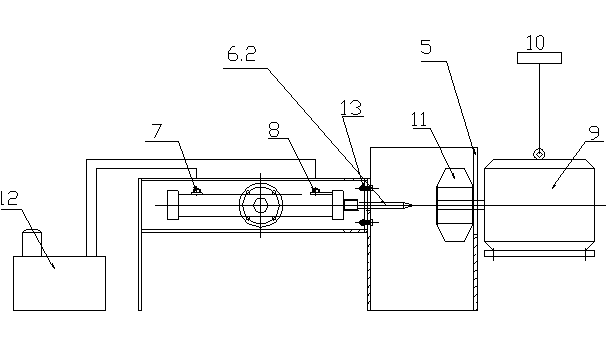
[0011] The specific implementation manners of the present invention will be described below in conjunction with the accompanying drawings. The invention discloses a hydraulic coupler dismounting device, which is also used for completing the disassembly of the hydraulic coupler 11 and the motor 9 . The dismantling device includes a hydraulic coupling dismantling working chamber 1 and a hydraulic cylinder 2 for placing the hydraulic coupler 11. The hydraulic cylinder 2 is fixed in the hydraulic cylinder fixing frame 3 through a fixing flange 4, and the hydraulic cylinder piston rod 6 is disassembled from the hydraulic coupling. The working chambers 1 are connected to each other, and the hydraulic coupler dismantling working chamber 1 also has a working surface 5 of the hydraulic coupler dismantling chamber that matches the force-bearing surface of the hydraulic coupler. The hydraulic cylinder 2 is connected in the hydraulic cylinder fixing frame 3 through a fixing flange 4 . Th...


PUM

PropertyMeasurementUnit
Thicknessaaaaaaaaaa

Abstract

The invention discloses a dismounting device for a hydraulic coupler. The dismounting device comprises a hydraulic coupler dismounting working chamber and a hydraulic cylinder, wherein the hydraulic coupler dismounting working chamber is used for accommodating the hydraulic coupler, the hydraulic cylinder is installed inside a hydraulic cylinder fixing frame, a piston rod of the hydraulic cylinder is connected with the hydraulic coupler dismounting working chamber, and the hydraulic coupler dismounting working chamber is provided with a hydraulic coupler dismounting working chamber working face which is matched with a stressed face of the hydraulic coupler. The dismounting device has the advantages that when the dismounting device is used for dismounting and separating the hydraulic coupler from a transmission shaft of an electric motor, the operation is simple, and the centering performance is good; during dismounting, the stressed face of the hydraulic coupler is uniform, and the hydraulic coupler and the electric motor are separated quickly under the condition that the hydraulic coupler and the electric motor are not damaged; the dismounting device is simple in structure, low in cost, safe and quick.

Description

technical field [0001] The invention relates to a dismantling device, in particular to a dismantling device capable of quickly dismantling a hydraulic coupling. Background technique [0002] Motor hydraulic couplers are widely used in various industries such as metallurgy, mining, and chemical industry. There is a gap of 0.03mm-0.05mm between the transmission hole in the normal hydraulic coupler and the motor drive shaft. Due to the long-term output of high-torque and high-speed rotation of the hydraulic coupling and its connected motor transmission in a high-temperature, dust-heavily polluted environment, the matching gap between the motor transmission shaft and the internal transmission hole of the hydraulic coupling will fail and bond. It is difficult to disengage the hydraulic coupling from the motor transmission shaft. The traditional disassembly method is to insert the inclined iron into the gap between the hydraulic coupler and the front end of the motor, and tap the...

Claims


Application Information

Patent Timeline
IPC IPC(8): B23P19/027
Inventor 张曙涛冯会玉王军崔刚戚大波王博李井磊郑振祥王合群李在勇张焕生陈强张风元刘仁国苏庆利李芳坤夏江波王萌袁望浪金立坤
Owner JIGANG GRP
Learn More