Wrist joint structure of underwater mechanical arm

An underwater manipulator and wrist joint technology, applied in the field of wrist joint structure, can solve problems affecting the movement of the underwater manipulator, large size, etc., and achieve the effects of light weight, simple structure, and low manufacturing and production costs

Inactive Publication Date: 2013-09-25
BEIHANG UNIV
View PDF5 Cites 13 Cited by
  • Summary
  • Abstract
  • Description
  • Claims
  • Application Information

AI Technical Summary

Benefits of technology

This patented technology allows for better control over robots that move around inside water without getting stuck or losing their power due to gravity forces when turning at angles greater than 90 degrees from one direction. It also provides more space efficient solutions compared to traditional methods like hydraulics or pneumatics.

Problems solved by technology

Technological Problem addressed in this patented technical problem relates to improving the design of a waterborne robot's arm called Weldon (Writann), where there may exist five different types of movements required during operation. These motions require precise orientation within certain limits while also requiring minimal energy consumption from the actuator(s). Additionally, some applications involve controllable motion over longer periods without losing accuracy. To achieve both goals, the hydrostatic driving component described in the patents requires excellent fluidity and durability, but current designs suffer issues including excessive inner leaks caused by imperfections in the construction materials themselves.

Method used


Image

  • Wrist joint structure of underwater mechanical arm
  • Wrist joint structure of underwater mechanical arm
  • Wrist joint structure of underwater mechanical arm

Examples


Embodiment Construction

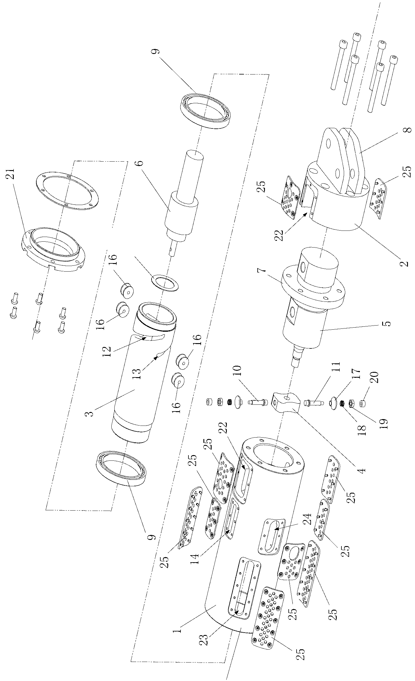
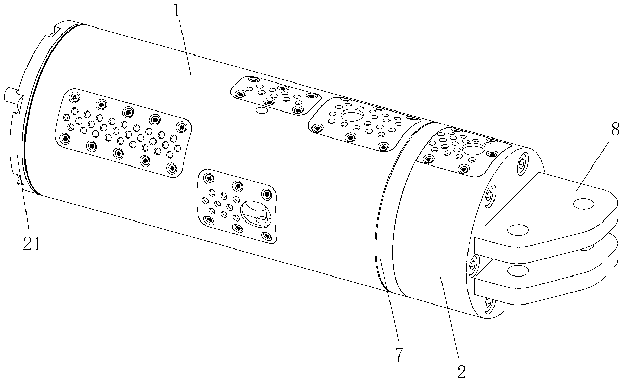
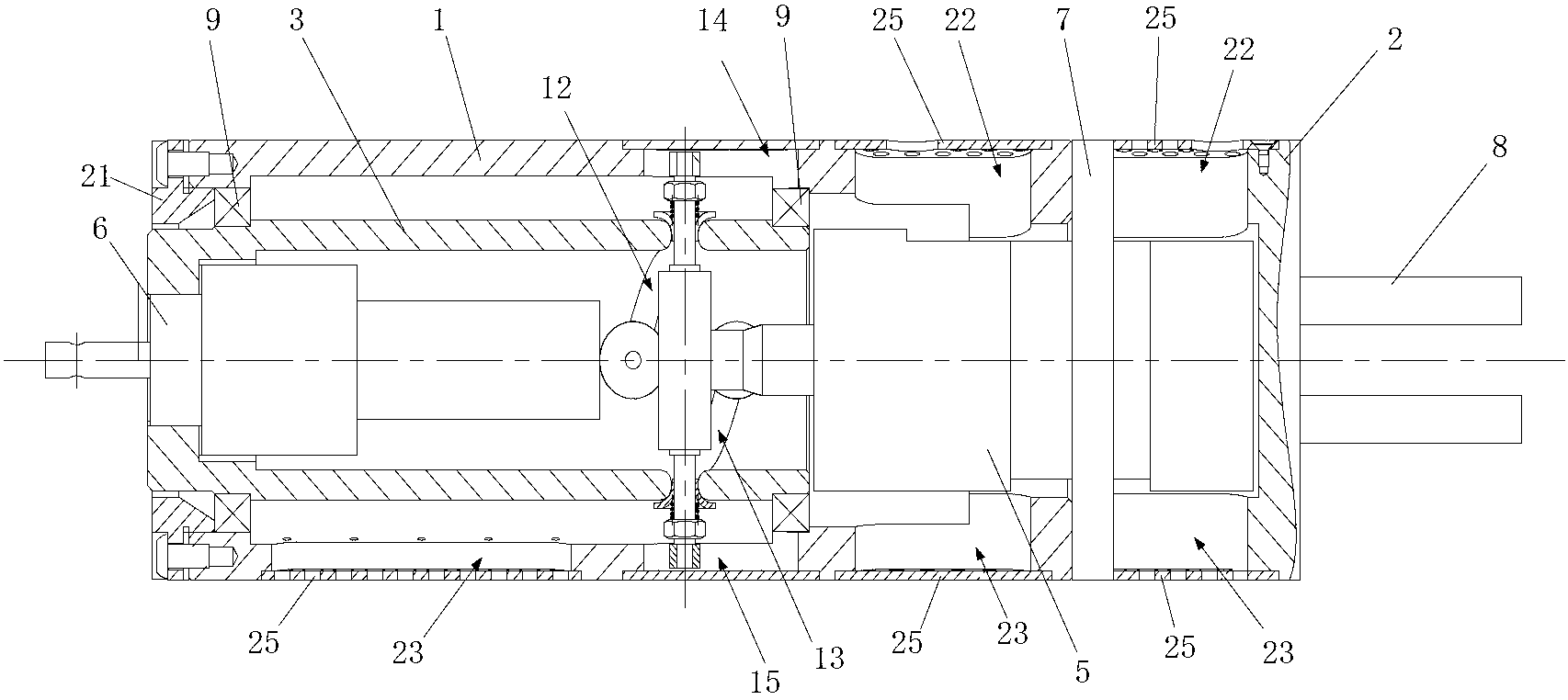
[0033] The present invention will be further described below in conjunction with the accompanying drawings.

[0034] The wrist joint structure of the present invention includes an outer cylinder 1, a tail cover 2, a cam cylinder 3, a pin disc 4, a first hydraulic cylinder 5 and a second hydraulic cylinder 6, such as figure 1 , figure 2 , image 3 shown.

[0035] Among them, the rear end of the outer cylinder 1 is fixedly connected with the tail cover 2 through the flange 7 provided in the axial direction of the first hydraulic cylinder 5, thereby forming an integral cylindrical wrist joint shell; thus the first hydraulic cylinder 5 is fixed on the wrist joint Inside the casing, and the piston rod of the first hydraulic cylinder 5 faces the front end of the cam cylinder 3 . An articulation frame 8 is designed on the end face of the tail cover 2, which is used to realize the connection between the wrist joint structure of the present invention and the joint of the underwater...


PUM


Abstract

The invention discloses a wrist joint structure of an underwater mechanical arm. The wrist joint structure comprises an outer cylinder, a tail cover, a cam cylinder, a pin disk, a first hydraulic cylinder and a second hydraulic cylinder, wherein a cylindrical wrist joint casing is formed between the outer cylinder and the tail cover, the first hydraulic cylinder and the cam cylinder are installed inside the cylindrical wrist joint casing, and the second hydraulic cylinder is installed inside the cam cylinder. The pin disk is sleeved on a piston rod of the first hydraulic cylinder, and pins are connected above and under the pin disk and arranged inside a spiral cam groove which is formed in the cam cylinder and a guiding groove which is formed axially in the outer cylinder respectively, thus, under the guidance of the guiding groove, the first hydraulic cylinder drives the pin disk and the pins to move linearly, the linear movement is converted into the rotation movement of the cam cylinder through the cam groove, and an end actuator and the second hydraulic cylinder which are installed on the cam cylinder are driven to rotate. The wrist joint structure has the advantages of being capable of achieving limited-angle rotation within 360 degrees and providing a linear driving force outwards, simple and compact in structure, small in size, light in weight and low in manufacturing and production cost.

Description


Claims


Application Information

Patent Timeline
Owner BEIHANG UNIV
Why Eureka
Try Eureka