Cutting device

A cutting and conveying device technology, used in transportation and packaging, metal processing, sending objects, etc., can solve problems such as interference, position deviation, transmission and processing device interference, and achieve the effect of simple speed adaptation and simple transfer

Active Publication Date: 2013-09-25
MULLER MARTINI HLDG
View PDF7 Cites 2 Cited by
  • Summary
  • Abstract
  • Description
  • Claims
  • Application Information

AI Technical Summary

Problems solved by technology

Therefore, when the product speed is too high relative to the speed of the conveying system of the downstream processing device, the product is braked uncontrollably and thus leads to a positional deviation of the product in the conveying direction.
These positional deviations are int

Method used


Image

  • Cutting device
  • Cutting device
  • Cutting device

Examples


Embodiment Construction

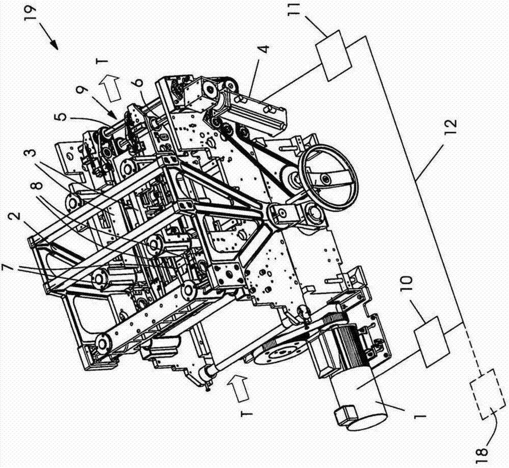
[0021] A representative example of a cutting device 19 for edge cutting according to the prior art with separate drive means is shown in FIG. 1A . The first drive motor 1 realizes the movement of the upper cutter bridge 2 on which the upper cutter is fixed. The direction of product movement is indicated by arrow T. The second drive motor 4 drives the belts 7 , 8 of the conveyor system 9 via continuous first and second drive shafts 5 , 6 . For the two drive motors 1 , 4 are provided control units 10 , 11 which can communicate with each other by means of a connection to exchange data and / or control signals. Furthermore, the connection 12 can also lead to a central machine control unit 18 .

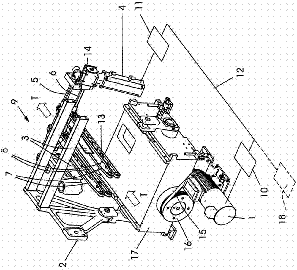
[0022] The main elements of the drive that realize the two motion sequences can be seen in FIG. 1B . The first drive motor 1 realizes the vertical non-uniform oscillating movement of the upper knife bridge 2 by means of the toothed belt 15 of the toothed belt pulley 16 and the transmissio...


PUM


Abstract

The present invention relates to a device for simultaneous three-sided trimming of products in a plurality of cutting stations, comprising: a common upper knife carrier operable in a stroke motion, wherein at least blades for front edge trimming and for top and bottom trimming of the products are mounted on the upper knife carrier; a first drive for driving the upper knife carrier and a conveyor device, wherein the conveyor device has top-related and bottom-related pairs of conveyor belts for conveying the products through the cutting stations of the device; at least one second drive for driving the conveyor device, wherein the drives used for a stroke device and the conveyor device are each implemented as self-contained mutually independent drives, and connected to one another by control devices. The device has another collecting conveyor device downstream of the conveyor device for conveying the products through the cutting stations in a conveying direction of the products, wherein the collecting conveyor device has a self-contained and independent drive, the drive is connected with the other independent drives of the device through control devices.

Description

technical field [0001] The invention relates to a device and a method for simultaneously cutting a product on three sides according to claim 1 or the preamble of claim 5 . Background technique [0002] During booklet production, the pages are collated on a collating and binding machine and the bound product is trimmed in a device for trimming on three sides, for example a shredder. This is achieved in the cutting station for cutting the front edge and cutting the top or foot by means of an upper knife which moves relative to a fixed lower knife or cutting strip. [0003] Such a shredder is known, for example, from EP1152310A1. The shredder has an upper knife bridge which can be driven with a stroke movement by means of a servomotor. On the upper cutting knife bridge, be fixed with the upper cutting knife that is used for front edge cutting and is used for sky head cutting and ground foot cutting. Here, the cutting of the front edge takes place in a first cutting station, ...

Claims


Application Information

Patent Timeline
IPC IPC(8): B26D5/20B26D1/09B26D7/32B26D7/06
CPCB26D5/00B26D2007/0081B26D2007/322B65H29/12B65H2301/4229B65H2701/1932
Inventor W·马特斯A·施泰纳特
Owner MULLER MARTINI HLDG
Why Eureka
Try Eureka