
Electric guide plate and torque protection device thereof

A protection device and guide plate technology, which is applied in the direction of safety devices, transportation and packaging, load suspension components, etc., can solve problems such as damage, internal components and drive components of the reduction box, and achieve the effect of ensuring versatility and uniform dimensions

Active Publication Date: 2013-09-25
SHANGHAI ZHENHUA HEAVY IND +1
View PDF4 Cites 4 Cited by
  • Summary
  • Abstract
  • Description
  • Claims
  • Application Information

AI Technical Summary

Problems solved by technology

[0002] An important and difficult part in the electric spreader is the guide plate mechanism. The reliability of the guide plate parts directly affects the working efficiency and reliability of the whole machine. The traditional hydraulic guide plate mechanism can release overload through the overflow protection of the hydraulic valve. However, because the brakes of electric products do not have this function, the strong impact during operation may easily cause damage to the internal components and driving components of the guide plate deceleration box. For this reason, a torque of the electric guide plate mechanism is required. Protection device by which the impact force is released, thus protecting the entire flipper mechanism

Method used


Image

  • Electric guide plate and torque protection device thereof
  • Electric guide plate and torque protection device thereof
  • Electric guide plate and torque protection device thereof

Examples


Embodiment Construction

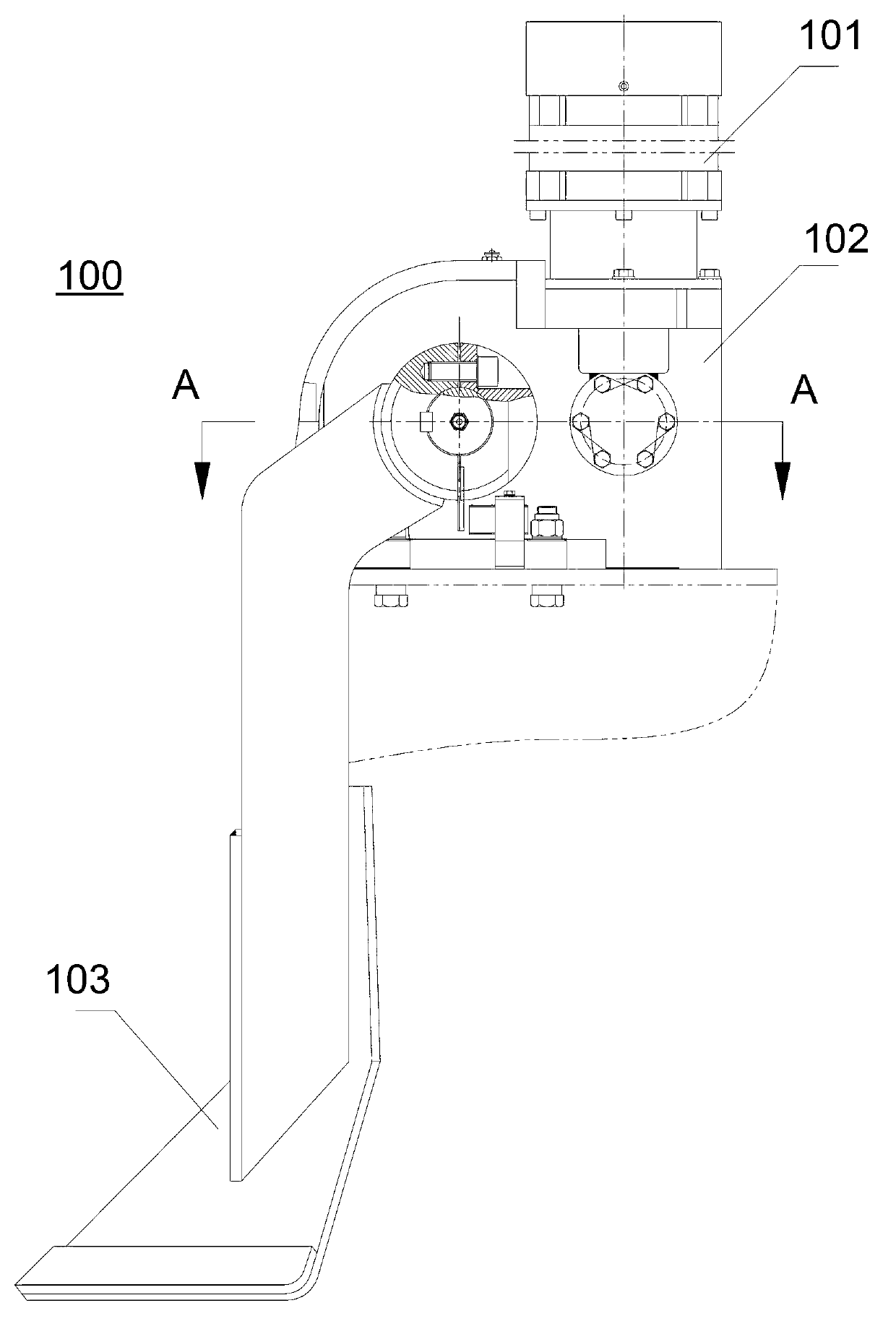
[0018] refer to figure 1 as shown, figure 1 Disclosed is a general assembly diagram of an electric guide plate mechanism according to an embodiment of the present invention. This electric guide plate mechanism 100 includes a drive motor 101, a gear box 102 and a guide plate structure 103, the drive motor 101 is connected to the guide plate structure 103 through the gear box 102, and the drive motor 101 rotates to drive the guide plate structure 103 to swing up and down, for example, to swing up and down 180° .

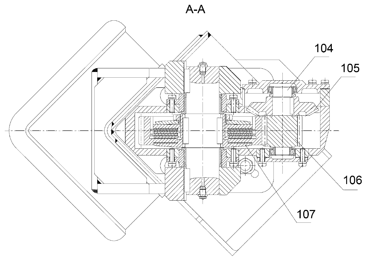
[0019] refer to figure 2 as shown, figure 2 revealed figure 1 View from direction A-A in the embodiment shown. The gear box 102 includes a gear shaft 104 , a bevel gear 105 , a pinion 106 and an electric flipper torque protection device 107 . The driving motor 101 is connected to the bevel gear 105 and drives the bevel gear 105 to rotate. The bevel gear 105 is connected to the pinion gear 106 through the gear shaft 104. The pinion gear 106 meshes with the teeth...


PUM


Abstract

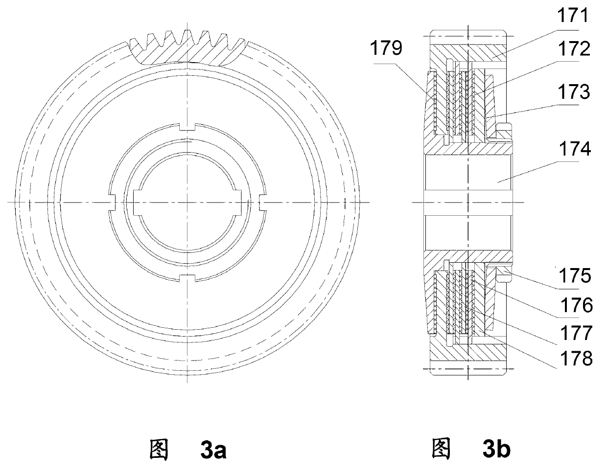
The invention discloses a torque protection device of an electric guide plate. The torque protection device comprises a rotating sleeve, an inner backing plate, an outer backing plate, a pressing plate, a bull gear, friction plates and spring parts. The rotating sleeve is connected with a transmission shaft, and is used for transmission; the inner backing plate and the pressing plate are connected to the rotating sleeve, and rotate with the rotating sleeve; the outer backing plate is connected to the bull gear, and rotates with the bull gear; the friction plates are arranged among all the fitting surfaces of the rotating sleeve, the inner backing plate, the outer backing plate, the pressing plate and the bull gear, so that torque transmission is performed among the fitting surfaces by frictional force. The spring pats are used for pressing the bull gear, the inner backing plate, the pressing plate, and the outer backing plate against the rotating sleeve firmly, and the spring parts are locked on the rotating sleeve. When the torque protection device of the electric guide plate is subjected to external impact force, and the impact force exceeds a friction torque threshold of the friction plates, the fitting surfaces will slide relatively to release the impact force. An internal friction fitting position is employed to release overloaded impact force, so that a problem of conventional electric guide is solved, wherein the problem is that parts are damaged because of hard transmission performed directly through a gear mechanism.

Description

technical field [0001] The invention relates to the field of container cranes, in particular to an electric guide plate mechanism for a spreader and a moment protection device thereof. Background technique [0002] An important and difficult part in the electric spreader is the guide plate mechanism. The reliability of the guide plate parts directly affects the operating efficiency and reliability of the whole machine. The traditional hydraulic guide plate mechanism can release overload through the overflow protection of the hydraulic valve. However, because the brakes of electric products do not have this function, the strong impact during operation may easily cause damage to the internal components and driving components of the guide plate deceleration box. Therefore, a torque of the electric guide plate mechanism is required. A protection device by which the force of the impact is released, thereby protecting the entire flipper mechanism. Contents of the invention [0...

Claims


Application Information

Patent Timeline
IPC IPC(8): B66C15/00
Inventor 马云飞徐坤沈彪
Owner SHANGHAI ZHENHUA HEAVY IND
Learn More