Method for production of solid electrolyte and solid electrolytic capacitor

a solid electrolyte and capacitor technology, applied in the manufacture of electrolytic capacitors, electrolytic capacitors, coatings, etc., can solve the problems of large capacity of solid electrolyte capacitor chips, inability to obtain large capacity, and undesirable enhancement of equivalent series resistance, so as to avoid short-circuiting in capacitor elements, uniform shape and dimension, and stably manufactured

Active Publication Date: 2011-11-24
MURATA MFG CO LTD
View PDF3 Cites 1 Cited by
  • Summary
  • Abstract
  • Description
  • Claims
  • Application Information

AI Technical Summary

Benefits of technology

[0047]According to the production method of the present invention, a thin solid electrolyte capacitor element having uniform shape and dimension can be stably manufactured while avoiding an increase of short-circuiting in the capacitor element.
[0048]The solid electrolyte formed on a dielectric film of a substrate for a solid electrolyte capacitor by the production method of the present invention exhibits a high adhesion to the dielectric film, has a large capacity and exhibits a reduced dielectric loss factor (tan δ), a reduced leakage current and a low fraction defective.
[0049]The thin solid capacitor element obtained from the solid electrolyte can give multilayer solid electrolyte capacitors having a high capacity provided that an increased number of the capacitor elements are superposed, and exhibiting a minimized unevenness in equivalent series resistance.

Problems solved by technology

Unless the polymerization conditions are precisely controlled, the adhered conductive polymer layers for forming the cathode portions of the capacitor become uneven in thickness and, in thin portions of the adhered polymer layers, a conductive paste is often contacted directly with a dielectric oxide layer, leading to leakage of current.
However, in the case when the conductive polymer layers have a large thickness, the number of capacitor elements to be superposed to a chip is limited and thus a solid electrolyte capacitor chip having a large capacity is difficult to obtain.
Further, when the adhered conductive polymer layers for forming the cathode portions of the capacitor are uneven in thickness, the effective contact area between the adjacent capacitor elements becomes small, which leads to undesirable enhancement in equivalent series resistance (ESR)
However, the polymerization under such conditions remarkably reduces the productivity.

Method used


Image

  • Method for production of solid electrolyte and solid electrolytic capacitor
  • Method for production of solid electrolyte and solid electrolytic capacitor
  • Method for production of solid electrolyte and solid electrolytic capacitor

Examples


example 1

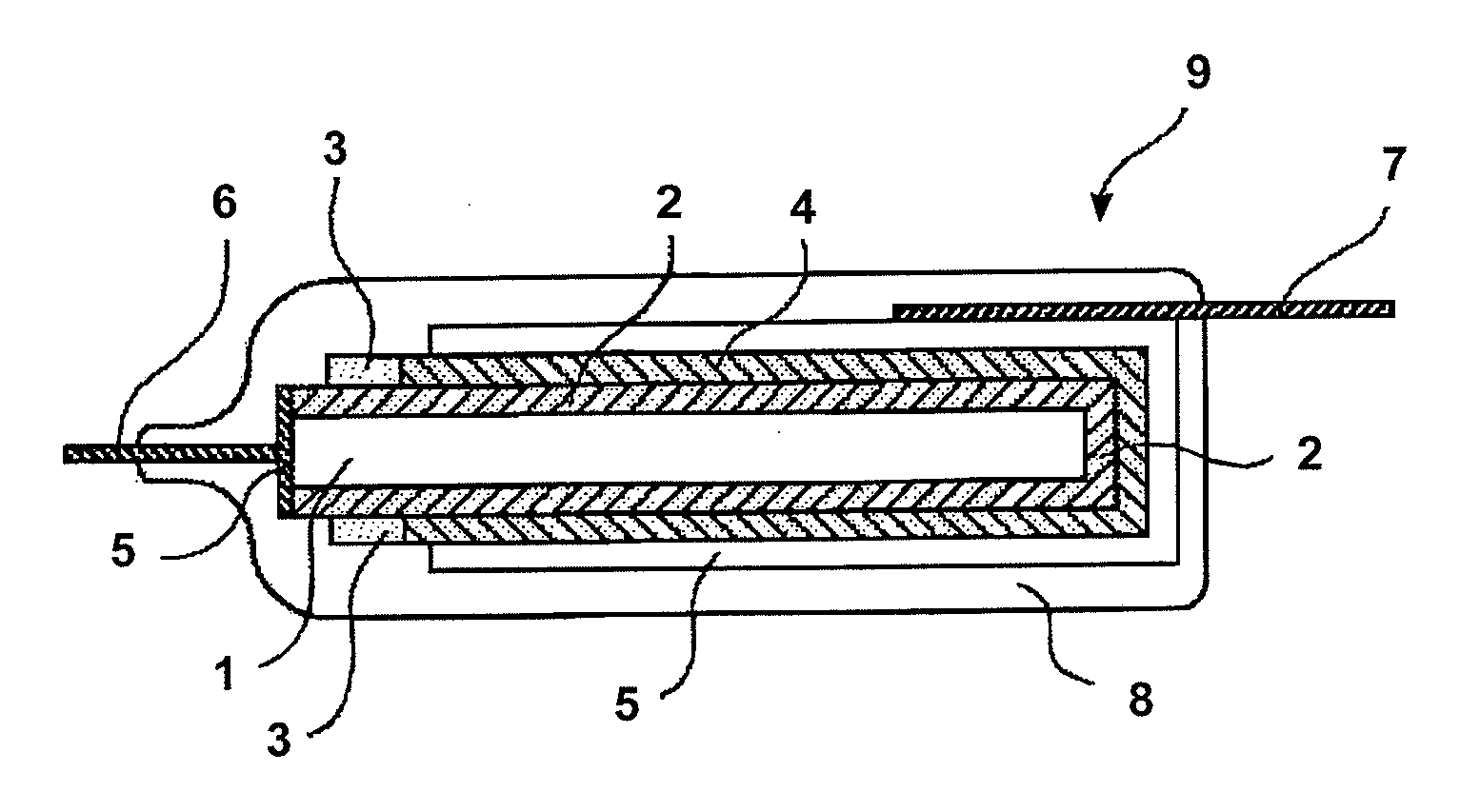
[0157]A chemically formed aluminum foil with a thickness of 100 μm was cut into strips each with a width of 3 mm and a length of 10 mm. Each strip was coated with a polyimide solution so that a linear coating of the polyimide solution with a width of 1 mm was formed which belted the strip at a position 4 mm apart from one end thereof and 5 mm apart from the other end thereof (thus, each strip was divided into two parts, one of which had a 3 mm×4 mm size and the other had a 3 mm×5 mm). The linear polyimide coating was dried to form a linear masking belting each strip. One part having a 3 mm×4 mm size of each aluminum foil strip was subjected to chemical formation using an aqueous ammonium adipate solution with a concentration of 10% by mass while a voltage of 4V was applied, whereby a dielectric oxide layer was formed on the cut periphery of the part having a 3 mm×4 mm size.

[0158]Oxidative polymerization of 3,4-ethylenedioxythiophene was carried out to form a solid electrolyte film o...

example 2

[0166]The procedures as described in Example 1 were repeated to make aluminum foil strips each having a solid electrolyte layer formed thereon, wherein the polymerizable monomer-containing solution used was changed to a solution in isopropyl alcohol (IPA) containing 25% by mass of 3,4-ethylenedioxythiophene, 0.007% by mass, as expressed in terms of the concentration of 3,4-ethylenedioxythiophene monomer, of 3,4-ethylenedioxythiophene dimer, and 0.001% by mass, as expressed in terms of the concentration of 3,4-ethylenedioxythiophene monomer, of 3,4-ethylenedioxythiophene trimer. The value as defined by the formula “A / (B+C)” (where A: concentration of the monomer, B: concentration of the dimmer as expressed in terms of the concentration of the monomer, and C: concentration of the trimer as expressed in terms of the concentration of the monomer) was 3.125. Further, the cycle comprising the dipping step and polymerization step was repeated 17 times instead of 19 times to form a solid el...

example 3

[0170]The procedures as described in Example 1 were repeated to make aluminum foil strips each having a solid electrolyte layer formed thereon, wherein the polymerizable monomer-containing solution used was changed to a solution in isopropyl alcohol (IPA) containing 30% by mass of 3,4-ethylenedioxythiophene, 0.2% by mass, as expressed in terms of the concentration of 3,4-ethylenedioxythiophene monomer, of 3,4-ethylenedioxythiophene dimer, and 0.007% by mass, as expressed in terms of the concentration of 3,4-ethylenedioxythiophene monomer, of 3,4-ethylenedioxythiophene trimer. The value as defined by the formula “A / (B+C)” (where A: concentration of the monomer, B: concentration of the dimmer as expressed in terms of the concentration of the monomer, and C: concentration of the trimer as expressed in terms of the concentration of the monomer) was 145. Further, the cycle comprising the dipping step and polymerization step was repeated 17 times instead of 19 times to form a solid electr...


PUM

PropertyMeasurementUnit
wavelengthaaaaaaaaaa
electrically conductiveaaaaaaaaaa
concentrationaaaaaaaaaa

Abstract

A method for producing a solid electrolyte is disclosed, which comprises the steps of applying a solution containing a five-membered heterocyclic compound as a polymerizable monomer on a substrate surface, and polymerizing the applied monomer to give a solid electrolyte comprised of an electrically conductive polymer, wherein the monomer-containing solution contains the polymerizable monomer and at least one polymerizable compound selected from a dimer of the monomer and a trimer of the monomer, at a proportion satisfying the equation:A / (B+C)=100-1,000,000where A: concentration of the polymerizable monomer,B: concentration of the dimmer in terms of the concentration of its monomer, andC: concentration of the trimer in terms of the concentration of its monomer. In another aspect, a method is disclosed wherein a solution of a compound having a thiophene skeletal structure, which solution has a light absorbance of 1.5-10 at 300-340 nm, is applied on a substrate surface and polymerized.

Description

CROSS-REFERENCE TO RELATED APPLICATION [0001]This application was filed pursuant to 35 U.S.C. 111(a) with claiming the benefit of filing date of U.S. Provisional Application Ser. No. 60 / 752,920 filed Dec. 23, 2005 under the provision of 35 U.S.C. 111(b) pursuant to 35 U.S.C. 119(e) (1).TECHNICAL FIELD [0002]This invention relates to a method for producing a solid electrolyte comprised of an electrically conductive polymer, and a solid electrolyte capacitor provided with the solid electrolyte.BACKGROUND ART[0003]A basic element of a solid electrolyte capacitor generally has a structure as illustrated in FIG. 1 and is manufactured by a process comprising the steps of forming an oxide layer (2) comprised of a dielectric on an anode substrate (1) comprised of a metal foil which is etched and has an enhanced specific surface area; forming solid semiconductor layers (4) (the solid semiconductor layers are hereinafter called “solid electrolyte” when appropriate) as confronting electrodes o...

Claims


Application Information

Patent Timeline
Patent Type & Authority Applications(United States)
IPC IPC(8): B05D5/12H01G9/02
CPCH01G9/028H01G9/15Y10T29/417H01G9/0036
Inventor SAIDA, YOSHIHIRO
Owner MURATA MFG CO LTD
Why Eureka
Try Eureka