Automotive electrical connector box

Inactive Publication Date: 2005-06-02
SUMITOMO WIRING SYST LTD
View PDF7 Cites 1 Cited by
  • Summary
  • Abstract
  • Description
  • Claims
  • Application Information

AI Technical Summary

Benefits of technology

[0007] In light of the above described shortcomings, the automotive electrical connector box of the present invention is constructed to lower manufacturing costs an

Problems solved by technology

Manufacturing cost will increase if the core wire strand diameter is less than 0.24 mm due to the increased number of strands, and a core wire strand diameter greater than 0.4 mm will result in fewer core strands which will make it more difficult to compress the wire when inserted into the press

Method used


Image

  • Automotive electrical connector box
  • Automotive electrical connector box
  • Automotive electrical connector box

Examples


first embodiment

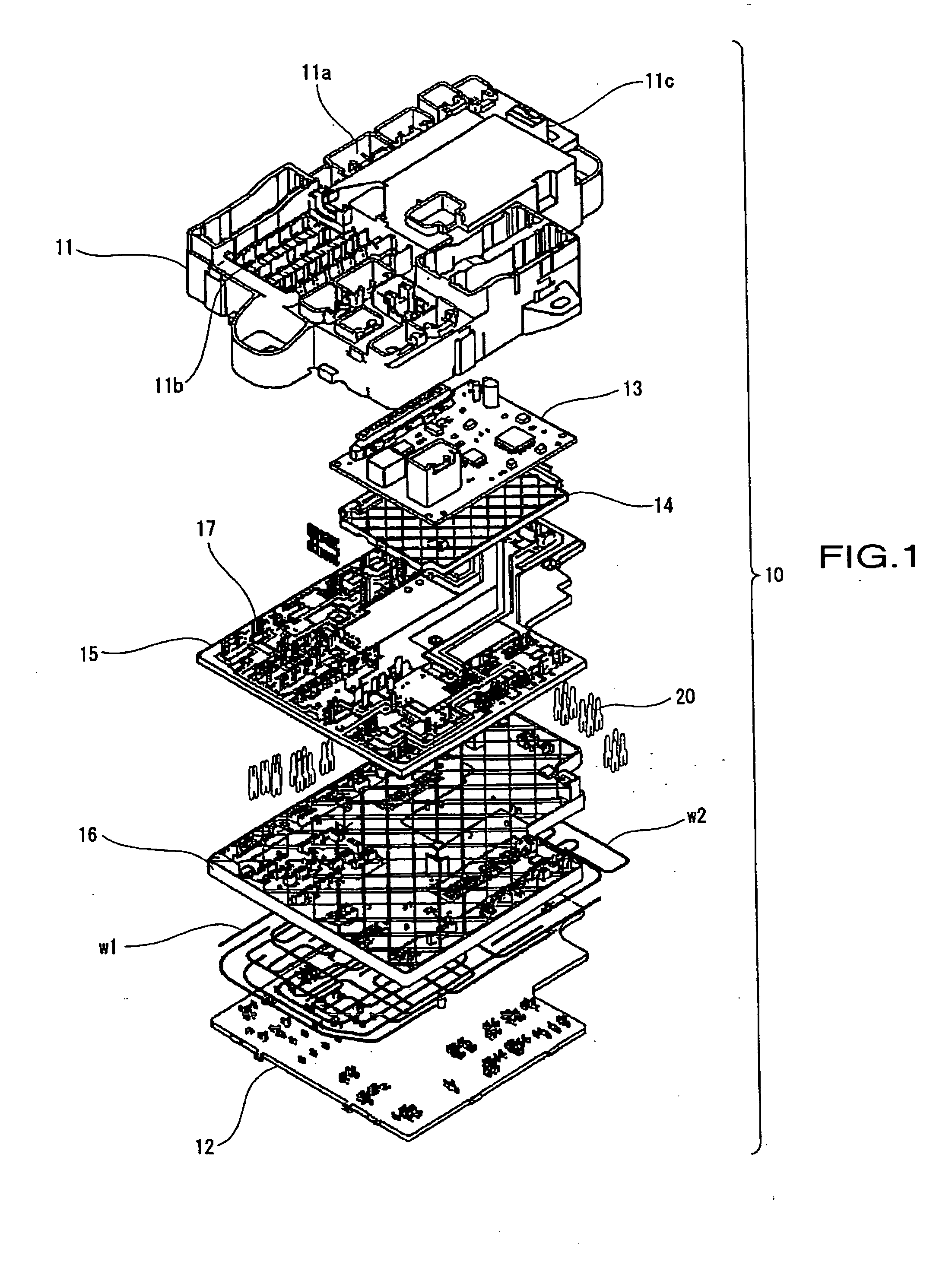
[0033] The following will describe embodiments of the invention with reference to the drawings. FIGS. 1 through 6 illustrate the invention.

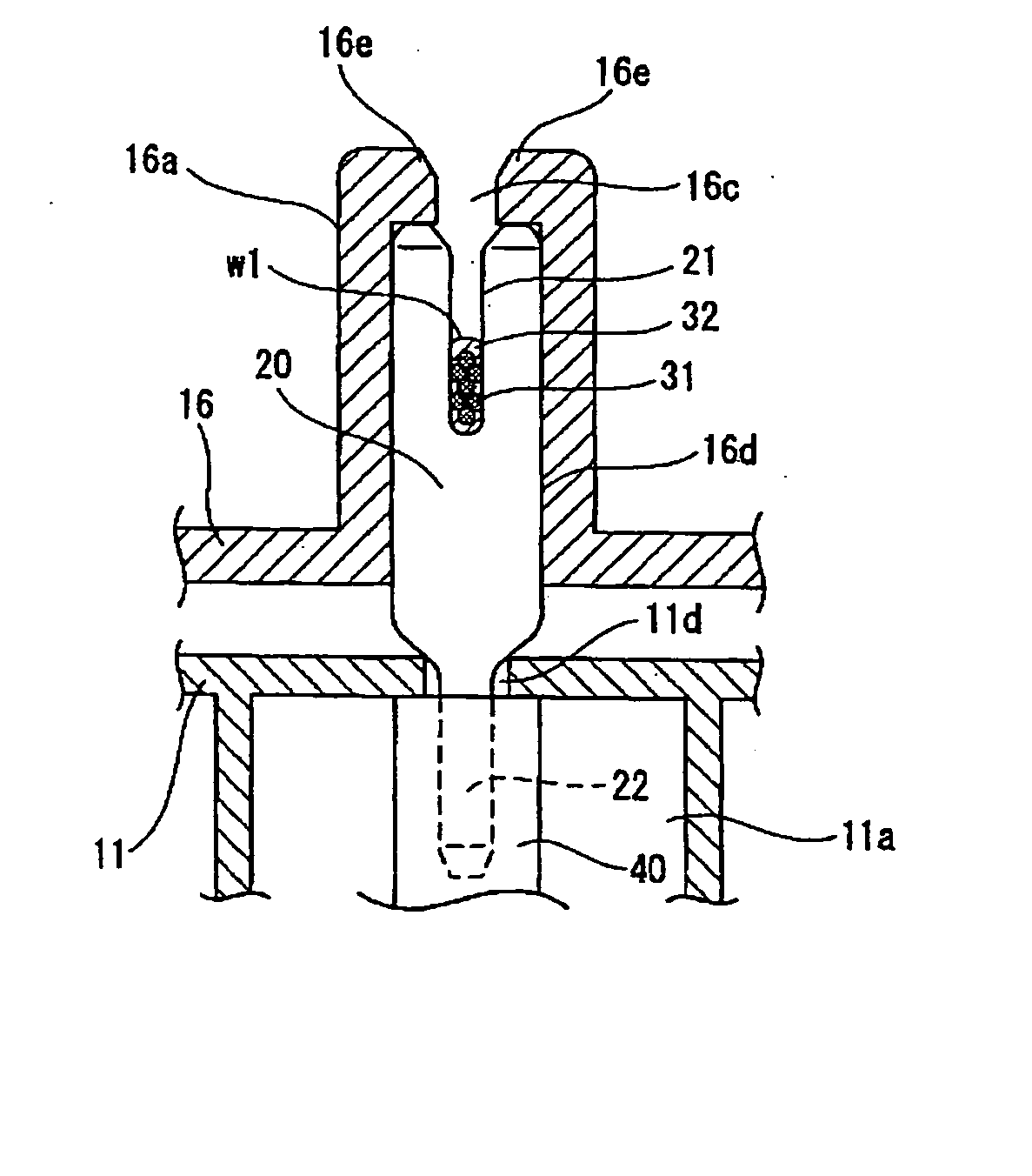
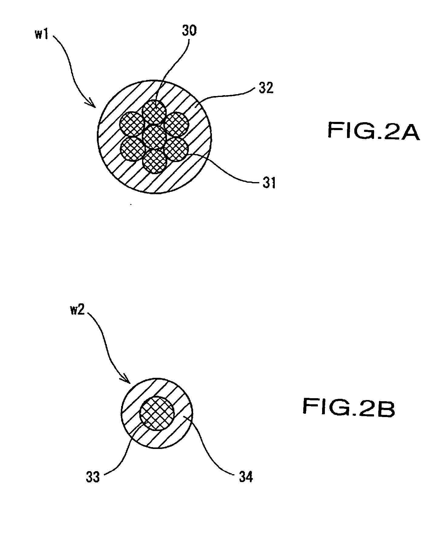
[0034] As illustrated in FIG. 1, electrical connector box 10 includes printed circuit board 13 and resin insulator boards 14, 15, and 16 arranged in layers within a container structure formed by upper case 11 and lower case 12 which are made from a synthetic resin material. Thick electrical wire w1 and thin electrical wire w2 (hereafter referred to as thick wire w1 and thin wire w2) are positioned on the underside of insulator board 16 and gripped by commonly dimensioned pressure contact terminals or insulation displacement terminals 20 which are able to grip either thick wire w1 or thin wire w2. Connector compartment 11a, fuse compartment 11b, and relay compartment 11c are formed on an external side of upper case 11. Moreover, bus bar 17, which has been press-blanked and bend-formed to the required shape from electrically conductive sheet metal,...

second embodiment

[0043]FIGS. 8A and 8B illustrate the present invention including pressure contact terminals 50 and 60 in which slots 51 and 61 are provided on one end, and external terminals 52 and 62 are provided on the other end. Although similar to pressure contact terminal 20 of the first embedment, pressure contact terminals 50 and 60 include a 90 degree angle between slots 51 and 61 and external terminal portions 52 and 62. The angle in the pressure contact terminals 50, 60 may be formed in any suitable manner and in the present embodiment have been bend formed 90 degrees between slots 51, 61 and external terminal parts 52, 62. On pressure contact terminal 50, the distance from the end of slot 51 to bent portion 53, and the distance from external terminal 52 to bent portion 53 are of a shorter dimension. On pressure contact terminal 60, the distance from the end of slot 61 to bent portion 63, and the distance from external terminal 62 to bent portion 63 of pressure contact terminal 60 are of ...


PUM


Abstract

An electrical connector box including a pressure contact terminal to connect to electrical wires of various diameters. A container including an upper case and lower case houses electrical wires which are gripped by slots of pressure contact terminals. Either a thick wire, which includes a core wire including multiple twisted strands, or a thin wire, which includes a single core wire, are able to connect to the uniform width slots of the pressure contact terminals.

Description

CROSS REFERENCE TO RELATED APPLICATIONS [0001] The present disclosure relates to subject matter contained in priority Japanese Application No. 2003-403584, filed on Dec. 2, 2003, which is herein expressly incorporated by reference in its entirety. BACKGROUND OF THE INVENTION [0002] 1. Field of the Invention [0003] The invention relates to an automotive electrical connector box, and more particularly, to an automotive electrical connector box including pressure contact terminals connecting terminals that grip electrical wires of varying diameter. [0004] 2. Description of Background Information [0005] As shown in FIG. 9, a conventional automotive electrical connector box is disclosed by Japanese Kokai (Laid Open) Patent No. 8-45570. In the conventional automotive electrical connector box, electrical wires are gripped by pressure contact terminals, each electrical wire including a core conductor enveloped by a layer of insulating material. This structure incorporates wire channels 2 an...

Claims


Application Information

Patent Timeline
IPC IPC(8): H01R4/24H01R13/46H01R9/24H02G3/16
CPCH01R4/2429H01R2201/26H01R9/2458H01R13/46
Inventor SAKA, YUUJI
Owner SUMITOMO WIRING SYST LTD
Why Eureka
Try Eureka