
Display substrate and display device

A technology for display substrates and transparent substrates, applied in identification devices, organic semiconductor devices, instruments, etc., can solve the problems of inconsistent threshold voltage shift, TFT stability decline, unfavorable high-resolution development, etc., to achieve high-resolution, area Reduce and increase the effect of display color gamut

Active Publication Date: 2015-08-19
BOE TECH GRP CO LTD +1
View PDF11 Cites 0 Cited by
  • Summary
  • Abstract
  • Description
  • Claims
  • Application Information

AI Technical Summary

Problems solved by technology

[0003] However, as the current display field develops toward high brightness, high resolution, and high color gamut, OLED displays have shown their limitations in high resolution and high color gamut.
In an OLED display, the threshold voltage of a thin-film transistor (TFT) that drives the OLED to emit light is related to many factors, including the doping of the TFT drain, the thickness of the dielectric, the material of the gate, and the excess charge in the dielectric. However, the current display substrate especially In the production process of large-scale display substrates, it is difficult to achieve the consistency of these factors due to the limitations of process conditions and levels, resulting in inconsistent threshold voltage shifts of each TFT. In addition, long-term work will also lead to a decrease in TFT stability.
Therefore, in order to ensure the uniformity of the brightness of the OLED display panel, an additional compensation circuit is required to compensate the inconsistency (or offset) of the compensation threshold voltage of each TFT. However, most compensation circuits need to use 4 to 6 TFTs, 1 to 2 storage capacitors, the pixel size is generally relatively large, which is not conducive to the development of high resolution

Method used


Image

  • Display substrate and display device
  • Display substrate and display device
  • Display substrate and display device

Examples


Embodiment

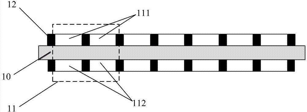
[0037] An embodiment of the present invention provides a display substrate, such as figure 1 As shown, the display substrate includes: a transparent substrate 10, a plurality of display pixels 11 arranged on the transparent substrate 10, each display pixel includes:

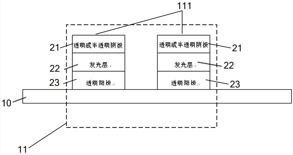
[0038] The transparent and self-illuminating first sub-pixel 111 is arranged on the front side of the transparent substrate 10;

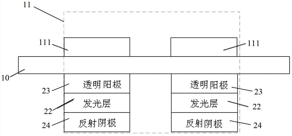
[0039] The self-illuminating second sub-pixel 112 is disposed on the back of the transparent substrate 10 , and the light emitting direction of the second sub-pixel 112 includes a direction pointing to the front of the transparent substrate 10 , that is, an upward direction as shown.

[0040] The front side of the transparent substrate 10 described in this embodiment refers to the surface on the side close to the light-emitting surface (viewing surface) of the display substrate, that is, figure 1 The upper surface of the transparent substrate 10 is shown, and the back of the transpare...


PUM


Abstract

A display panel and a manufacturing method therefor, and a display device. The display panel comprises a transparent substrate (10) and a plurality of display pixels (11), wherein the display pixels (11) are arranged on the transparent substrate (10). Each of the display pixels (11) comprises first subpixels (111) which are transparent and self-luminous and second subpixels (112) which are self-luminous. The first subpixels (111) are arranged on an out-light surface of the transparent substrate (10). The second subpixels (112) are arranged on a surface of the transparent substrate (10) opposite to the out-light surface, and out-light directions of the second subpixels (112) comprise a direction which points to the out-light surface of the transparent substrate (10).

Description

technical field [0001] The invention relates to the display field, in particular to a display substrate and a display device. Background technique [0002] Organic Light Emitting Diode (OLED) display has excellent characteristics such as self-illumination, high contrast, thin thickness, wide viewing angle, fast response speed, flexibility, wide operating temperature range, simple structure and manufacturing process, etc. An emerging technology considered to be the next generation of flat panel displays. [0003] However, as the current display field is developing towards high brightness, high resolution, and high color gamut, OLED displays have shown their limitations in high resolution and high color gamut. In an OLED display, the threshold voltage of a thin-film transistor (TFT) that drives the OLED to emit light is related to many factors, including the doping of the TFT drain, the thickness of the dielectric, the material of the gate, and the excess charge in the dielec...

Claims


Application Information

Patent Timeline
Patent Type & Authority Patents(China)
IPC IPC(8): G09F9/33
CPCH01L2251/5323H01L27/3218H01L27/3209H01L27/3213G09F9/33H10K59/32H10K59/351H10K59/353H10K2102/3031H10K50/81H10K50/82H10K71/00
Inventor 张春兵王峥徐利燕郤玉生
Owner BOE TECH GRP CO LTD
Learn More