
Terminal voice noise reducing method and terminal

A voice noise reduction and terminal technology, applied in voice analysis, telephone communication, instruments, etc., can solve the problems of poor call effect, affect call quality, and inability to improve call effect, and achieve the effect of improving the effect

Inactive Publication Date: 2013-09-25
MEIZU TECH CO LTD
View PDF4 Cites 25 Cited by
  • Summary
  • Abstract
  • Description
  • Claims
  • Application Information

AI Technical Summary

Problems solved by technology

[0004] In the case of little or no noise in the external environment, the existing technology cannot improve the call effect, and sometimes even affect the call quality
When the external environment is very quiet, since the external noise is very small or even negligible, there is a certain probability that the microphone specially used to capture external environmental noise will regard the user's normal call voice as external environmental noise and pass the noise The elimination algorithm is used to eliminate the user's call voice, so that the call effect will be deteriorated due to misoperation

Method used


Image

  • Terminal voice noise reducing method and terminal
  • Terminal voice noise reducing method and terminal

Examples


Embodiment 1

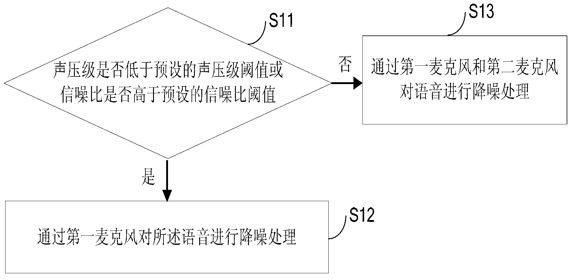
[0035] See figure 1 as shown, figure 1 Shown is a terminal voice noise reduction method, the terminal includes a first microphone and a second microphone, the method includes:

[0036] S11. Using the second microphone to determine whether the sound pressure level of the noise at the location of the terminal is lower than the preset sound pressure level threshold, or using the second microphone to determine whether the signal-to-noise ratio of the noise at the location of the terminal is higher than the preset SNR threshold;

[0037] Wherein, the first microphone is a main microphone and is used to collect voice and environmental noise; the second microphone is a secondary microphone and is used to collect environmental noise. The sound pressure level is the loudness of the sound, and its unit is decibel, which is a calculation unit to measure the loudness of the sound. The signal-to-noise ratio is the ratio of the normal sound signal to the noise signal when there is no sig...

Embodiment 2

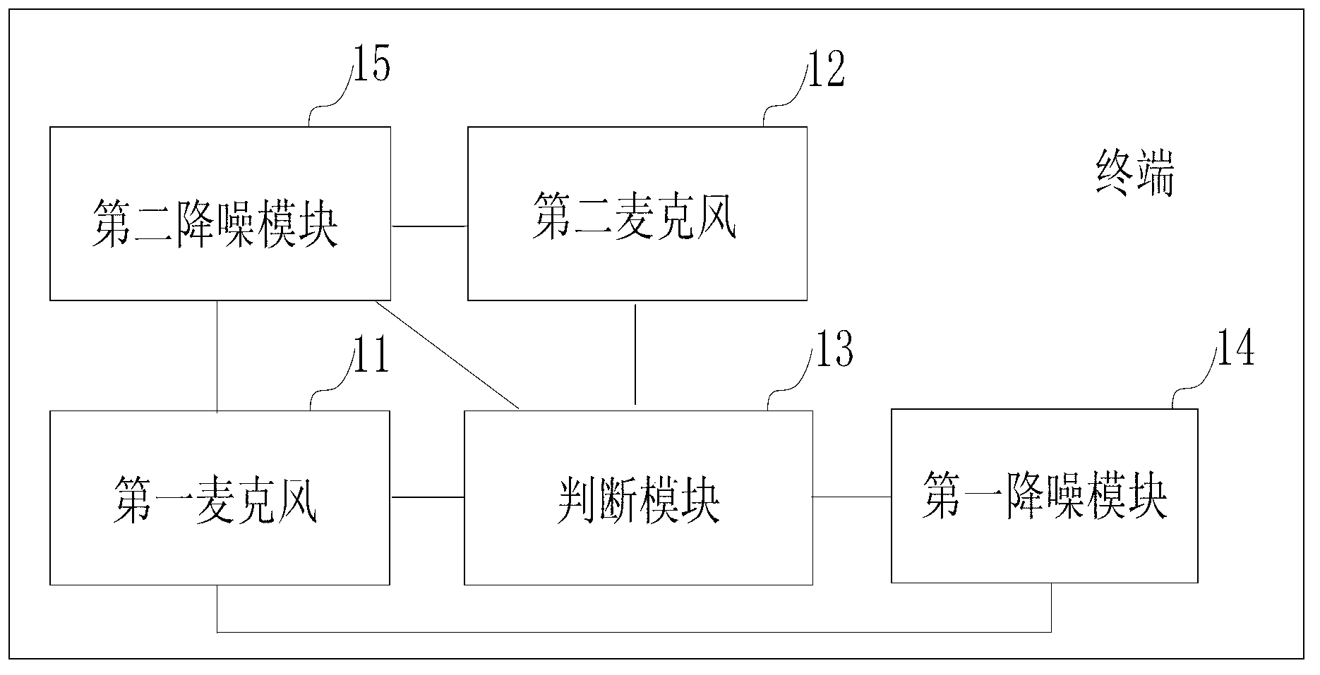
[0048] Such as figure 2 as shown, figure 2 It is a terminal proposed by the present invention, the terminal includes a first microphone 11 and a second microphone 12, and the terminal also includes: a judging module 13, which is used to judge whether the sound pressure level of the noise at the location of the terminal is low through the second microphone 12 At the preset sound pressure level threshold, or through the second microphone 12 to determine whether the signal-to-noise ratio of the noise at the location of the terminal is higher than the preset signal-to-noise ratio threshold; the first noise reduction module 14 is used for judging in the judgment module When the result is yes, the voice is subjected to noise reduction processing through the first microphone 11 .

[0049] Wherein, the first microphone 11 is a main microphone for collecting voice and environmental noise; the second microphone 12 is a secondary microphone for collecting environmental noise. The sou...


PUM


Abstract

The invention discloses a terminal voice noise reducing method and a terminal. The terminal comprises a first microphone and a second microphone. The terminal voice noise reducing method comprises the following steps of: judging whether the ambient environment is quiet or noisy by a sound pressure level or signal to noise ratio of the noise at the position in which the terminal is located, if a sound pressure level is lower than the preset sound pressure level threshold value or the signal to noise ratio is higher than a preset signal-to-noise ratio threshold value according to a detection result, judging the ambient environment of the terminal to be the quiet environment, and using the first microphone to carry out noise reduction treatment on voice. A condition that a sound sent by a user does not cause loss because of the noise reduction treatment is guaranteed, and a talking voice effect is improved.

Description

technical field [0001] The present invention relates to the technical field of speech signals, and more specifically, to a terminal speech noise reduction method and a terminal. Background technique [0002] Currently, manufacturers for manufacturing mobile terminals generally use a noise reduction method with dual microphones to improve the voice effect of mobile phone calls. The method of dual-microphone noise reduction is specifically to set two microphones on the call terminal, one of which is used to capture the voice of the call and the noise of the external environment, and the other microphone is specially used to capture the noise of the external environment, and then through the noise cancellation algorithm To eliminate the noise of the external environment, this can suppress the unsteady noise and get the best call effect. [0003] During the research and practice of the prior art, the inventors of the present invention have found that the prior art has the follo...

Claims


Application Information

Patent Timeline
IPC IPC(8): G10L21/02H04M1/725
Inventor 梁东明关鹏飞
Owner MEIZU TECH CO LTD
Learn More