Orthopedics-department joint replacement operation system

A joint replacement and surgery system technology, applied in the field of medical equipment, can solve the problems of the main machine's heavy weight, limited monitoring range, lack of Chinese interface, etc., and achieve the effect of easy operation and optimized effect

Inactive Publication Date: 2018-01-16
上海龙慧医疗科技有限公司
View PDF4 Cites 6 Cited by
  • Summary
  • Abstract
  • Description
  • Claims
  • Application Information

AI Technical Summary

Problems solved by technology

[0004] (1) Preoperative image modeling requires manual operation by professionals to delineate bone boundaries, which is time-consuming and laborious
[0005] (2) The process of registering the image and the patient's actual bone tissue in the actual spatial position during the operation is time-consuming
[0006] (3) Due to its physical characteristics, the optical positioning device is easily blocked and the monitoring range is limited, and the effect will be lost after the fixing frame is loose.
[0007] (4) The available prosthesis brands are limited to individual brands that match the sur

Method used


Image

  • Orthopedics-department joint replacement operation system

Examples


Example Embodiment

[0061] Example one

[0062] Orthopedic joint replacement surgery system, including mechanical arm assembly, scanner, pressure sensor, first position reflective array, second position reflective array, optical navigation device, console;

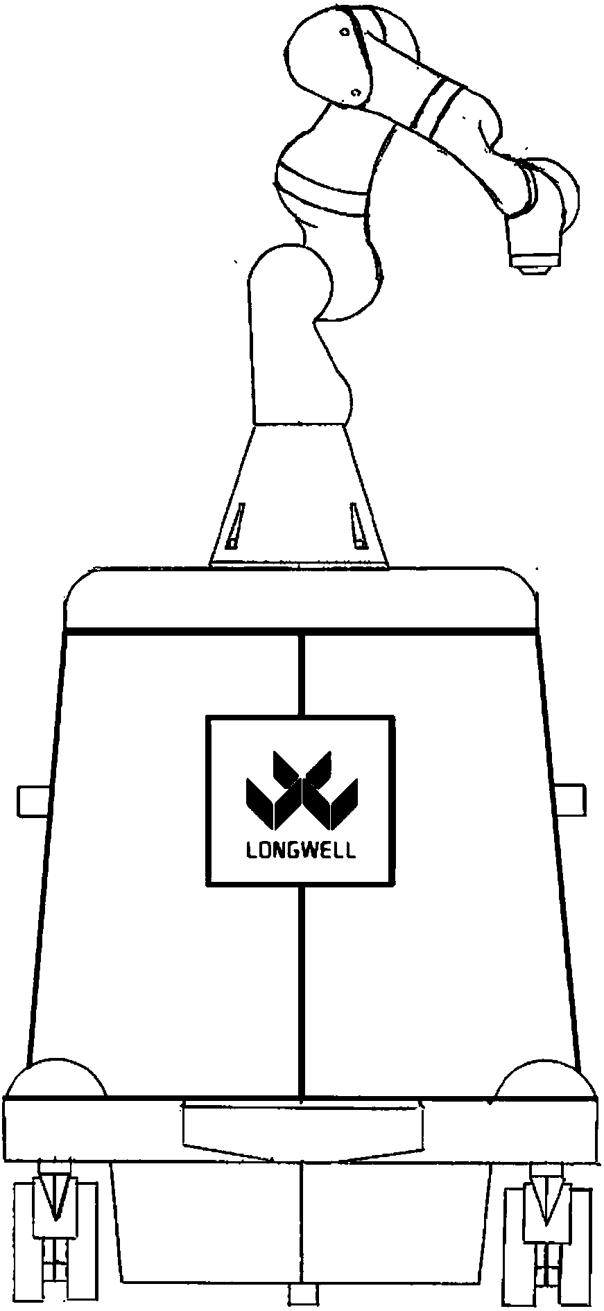
[0063] Such as figure 1 As shown, the mechanical arm assembly includes a mechanical arm;

[0064] The scanner is used for 3D scanning the real bone local geometric surface of the joint to be operated and sending the local figure of the joint to be operated to the console;

[0065] The first position reflection array is used for fixing at a bone joint;

[0066] The second position reflection array is used for positioning a mechanical arm;

[0067] The optical navigation device is used to emit detection light, and determine the position of the bone joint according to the reflection signal of the first position reflection array, and determine the position of the power tool fixed at the front end of the mechanical arm according to the reflection signal of ...

Example Embodiment

[0074] Example two

[0075] Based on the first embodiment, the orthopedic joint replacement surgery system further includes a probe;

[0076] The probe is provided with a probe position reflection device;

[0077] The optical navigation device, and capture the probe position signal reflected by the probe position reflector;

[0078] The console displays the corresponding positions of the real bone parts of the joints to be operated on the three-dimensional graphics of the joints to be operated on the surgical plan, and displays the probes in the three-dimensional graphics of the joints to be operated on the surgical plan according to the probe position signal. The overall orientation vector of the needle and the location of its tip.

[0079] In the orthopedic joint replacement surgery system of the second embodiment, the operator determines whether the position of the probe needle shown in the three-dimensional graphics of the joint to be operated on the operation plan is consistent wi...

Example Embodiment

[0080] Example three

[0081] Based on the orthopedic joint replacement surgery system of the first embodiment, the first position reflection array and the second position reflection array are each provided with at least four reflection devices;

[0082] The at least four reflecting devices are not on the same plane.

[0083] In the orthopedic joint replacement surgery system of the third embodiment, the first position reflector array and the second position reflector array are arranged in a three-dimensional manner, which can increase the transmission and acceptance range of the detection light, which can reach about 240°, and avoid poor tracking.


PUM


Abstract

The invention discloses an orthopedics-department joint replacement operation system. A control table comprises a display, and an operation plan is stored in the control table; the operation plan comprises a to-be-operated joint three-dimensional graph, a prosthesis model and three-dimensional graph and the position corresponding relationship and the whole force line relationship between a prosthesis and the to-be-operated joint; a to-be-operated-joint real-skeleton-local geometric curved surface obtained according to a scanner is matched with the to-be-operated joint three-dimensional graph in the operation plan through the control table, the actual position of the joint three-dimensional graph in the operation plan corresponding to a to-be-operated-joint real skeleton is traced, determined and traced in real time relying on infrared optical navigation, and the specific position of the prosthesis corresponding to a skeleton local is displayed on the to-be-operated joint three-dimensional graph in the operation plan. According to the orthopedics-department joint replacement operation system, the optimization matching speed of the to-be-operated-joint real skeleton local is high, and operation is easy.

Description

technical field [0001] The invention relates to medical equipment, in particular to an orthopedic joint replacement operation system. Background technique [0002] The existing joint surgery robot belongs to the auxiliary system that assists the interactive semi-active robot assisted by the mechanical arm to complete the operation. The system uses the preoperative CT image data of the patient to generate the preoperative plan; during the operation, the surgeon follows the preoperative plan. Manipulate the robotic arm and position the bone through the optical positioning device, so that under the guidance of real-time electronic images and tactile feedback, the power tool at the front end of the robotic arm can be used to accurately complete the osteotomy operation, providing guarantee for the precise implantation of the prosthesis; at the same time, during the operation It can also fine-tune the preoperative plan according to the quantitative evaluation results of the patien...

Claims


Application Information

Patent Timeline
IPC IPC(8): A61B34/30A61B34/20A61B34/10A61B17/16
Inventor 孙唯范卫东张海宁
Owner 上海龙慧医疗科技有限公司
Why Eureka
Try Eureka