Rotation type three-proofing insulator

An insulator and rotary technology, applied in the field of rotary three-proof insulators, can solve the problems of enhanced insulator flashover grounding, large manpower consumption, material and financial resources, economic losses, etc., and achieves stable and reliable operation, reduced manpower, and scientific design. Effect

Active Publication Date: 2013-09-25
STATE GRID CORP OF CHINA +1
View PDF5 Cites 5 Cited by
  • Summary
  • Abstract
  • Description
  • Claims
  • Application Information

AI Technical Summary

Problems solved by technology

Dust is easy to deposit on the surface of conventional insulators, and it is unevenly distributed on the shed of the insulator. Under adverse conditions such as fog, dew, and drizzle, flashover may occur on dirty insulators under low voltage. Insulation flashover accidents caused by pollution It is one of the main forms of power grid accidents, which has caused major economic losses to people's production and life every year; the wind-biased grounding of insulators means that the suspension insulators deviate from the vertical position to the iron tower body under strong wind conditions and cause a certain phase line to be grounded. In recent years, many such accidents have occurred on lines above 110kV, seriously affecting and threatening the safe operation of the power grid system; insulators in snowy weather are often covered with ice and snow, which increases the possibility of flashover grounding of insulators and poses a serious threat to the safe operation of the power grid
[0003] At present, insulators for high-voltage overhead lines in the power grid are basically divided into two types: pillar type and suspension type. Strengthening measures in the three aspects of coatings requires a lot of manpower, material and financial resources
In addition, there are currently no insulators with wind deflection resistance

Method used


Image

  • Rotation type three-proofing insulator
  • Rotation type three-proofing insulator
  • Rotation type three-proofing insulator

Examples


Embodiment Construction

[0021] The embodiments of the present invention will be described in detail below in conjunction with the accompanying drawings; it should be noted that the embodiments are illustrative, not restrictive, and cannot limit the protection scope of the present invention.

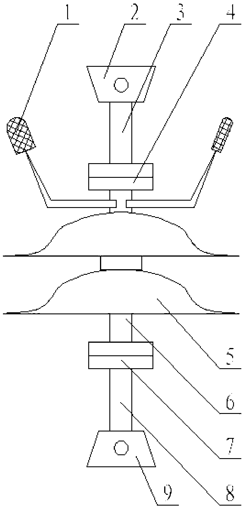
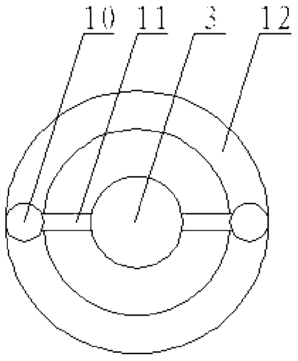
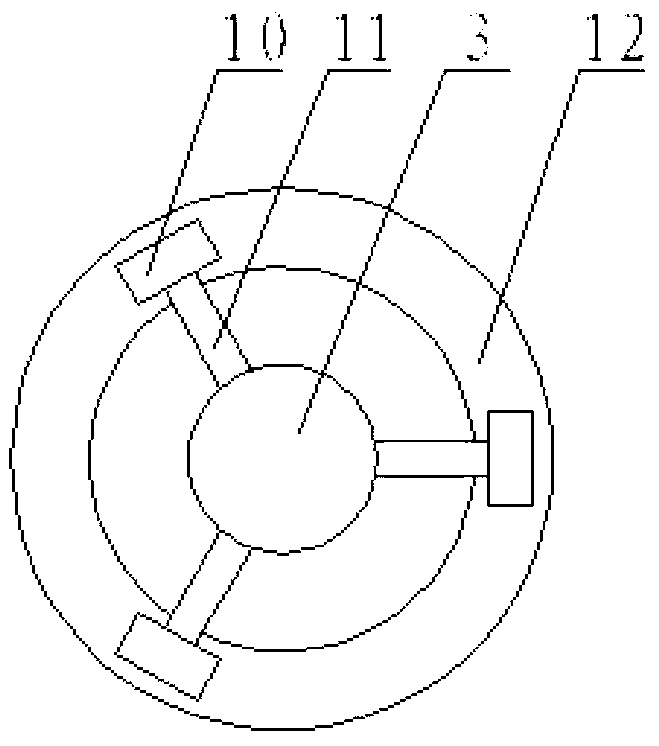
[0022] A rotary three-proof insulator includes a fixed handle 2, a suspension shaft, an insulator shed 5 and a suspension handle 9. The innovation of the present invention is: the fixed handle is installed on the upper end of the upper suspension shaft 3, and the lower end of the upper suspension shaft is rotatably installed in an upper rotation shaft 4, and the specific installation method is: an annular slide rail is arranged in the upper rotation shaft Slot 12, the lower end of the upper suspension shaft is evenly distributed along the circumferential direction with a set of slide rail bead shafts 11, each slide rail bead shaft is connected with a slide rail bead 10, and all slide rail beads are slidably insta...


PUM


Abstract

The invention relates to a rotation type three-proofing insulator which comprises a fixed handle, suspension shafts, an insulator umbrella skirt and a suspension line handle. The fixed handle is mounted at the upper end of the upper suspension shaft, and the lower end of the upper suspension shaft is rotatably arranged inside an upper rotating shaft. The suspension line handle is mounted at the lower end of the lower suspension shaft, and the upper end of the lower suspension shaft is rotatably mounted inside a lower rotation shaft. The upper rotating shaft and the lower rotating shaft are coaxially connected through a connecting shaft, and a rotating blade and the insulator umbrella skirt are coaxially mounted on the connecting shaft between the upper rotating shaft and the lower rotating shaft. The rotation type three-proofing insulator is scientific in design, reasonable in structure, easy to manufacture and convenient to use. Except for the basic functions of the insulator, the functions of fouling proofing, windage yaw proofing and ice coating proofing are achieved by the insulator through the effects of natural force and centrifugal force, and the purposes of improving the safety level of the insulator in a power grid and saving maintenance cost are achieved.

Description

technical field [0001] The invention relates to an insulator used for fixing lines and insulating in the field of power grid transmission equipment, in particular to a rotary three-proof insulator. Background technique [0002] Pollution flashover, wind-biased grounding, and ice-covered flashover are the three main reasons why insulators cause harm to the power grid. Dust is easy to deposit on the surface of conventional insulators, and it is unevenly distributed on the shed of the insulator. Under adverse conditions such as fog, dew, and drizzle, flashover may occur on dirty insulators under low voltage. Insulation flashover accidents caused by pollution It is one of the main forms of power grid accidents, which has caused major economic losses to people's production and life every year; the wind-biased grounding of insulators means that the suspension insulators deviate from the vertical position to the iron tower body under strong wind conditions and cause a certain phase...

Claims


Application Information

Patent Timeline
Patent Type & Authority Applications(China)
IPC IPC(8): H01B17/02H01B17/52
Inventor 管顺刚
Owner STATE GRID CORP OF CHINA
Why Eureka
Try Eureka