Resource allocation indicating method, resource allocation method and equipment
A technology of resource allocation and resource indication value, applied in the direction of sub-channel allocation of transmission path, allocation between users/terminals, separation device of transmission path, etc.
- Summary
- Abstract
- Description
- Claims
- Application Information
AI Technical Summary
Problems solved by technology
Method used
Image
Examples
Embodiment 1
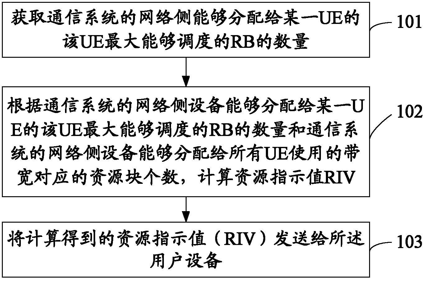
[0043] In this embodiment, it is assumed that the UE can support broadband, but the maximum number of resource blocks (RBs) that can be allocated to a certain UE by the network side equipment of the communication system is limited. For this type of UE, the resource allocation indication method provided in this embodiment includes the following steps, as figure 1 shown.
[0044] 101. Obtain the maximum number N of RBs that can be allocated to a certain UE by the network side equipment of the communication system. 0 .
[0045] In this step, the network-side device of the communication system can know that the UE is a low-cost UE through information interaction with the UE, and then know the maximum RB that the network-side device of the communication system can allocate to a certain UE. QuantityN 0 . The said network side equipment may be a base station (Node B).
[0046] Herein, the number of resource blocks (RBs) that can be allocated to the UE by the network side equipme...
Embodiment 2
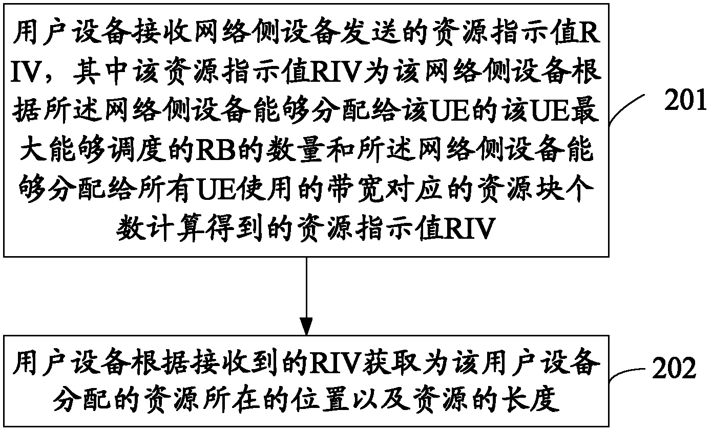
[0099] Based on the resource allocation indication method provided in the foregoing embodiments, this embodiment further provides a resource allocation acquisition method. Such as figure 2 As shown, the method includes the following steps.
[0100] Step 201, the user equipment receives the resource indication value RIV sent by the network side equipment, wherein the resource indication value RIV is the maximum number N of RBs that the network side equipment can allocate to the UE according to the maximum number of RBs that can be scheduled by the UE 0 The number N of resource blocks corresponding to the bandwidth that the network side device can allocate to all UEs RB Calculated resource indicator value RIV.
[0101] In this step, the bit number n of the binary number representing the calculated RIV bit satisfy
[0102] Wherein, the network side device carries the resource indication value RIV in the downlink control information DCI of the physical downlink control chan...
Embodiment 3
[0111] In this embodiment, it is assumed that the UE can only support narrowband downlink, and the narrowband is the baseband. For control information of the UE, a narrowband PDCCH, such as an enhanced PDCCH (enhanced PDCCH, e-PDCCH), is used for transmission, and the PDSCH can only be transmitted within this narrowband. For example, suppose UE narrowband only supports N 0 RB, the narrowband PDCCH and the corresponding PDSCH can only be in this N 0 Transmission within RB.
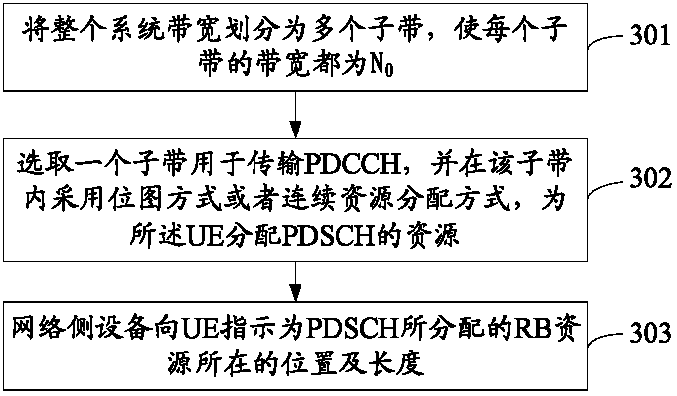
[0112] The UE resource allocation method provided in this embodiment includes the following steps, as image 3 shown.
[0113] 301. Divide the entire system bandwidth into multiple subbands, so that the bandwidth of each subband is N 0 .
[0114] The UE only supports a bandwidth of N 0 When the narrowband is narrow, the network side equipment of the communication system can divide the entire system bandwidth into multiple subbands, so that the bandwidth of each subband is N 0 .
[0115] 302. Select ...
PUM
 Abstract
Description
Claims
Application Information
 - R&D
- Intellectual Property
- Life Sciences
- Materials
- Tech Scout
- Unparalleled Data Quality
- Higher Quality Content
- 60% Fewer Hallucinations
Browse by: Latest US Patents, China's latest patents, Technical Efficacy Thesaurus, Application Domain, Technology Topic, Popular Technical Reports.
© 2025 PatSnap. All rights reserved.Legal|Privacy policy|Modern Slavery Act Transparency Statement|Sitemap|About US| Contact US: help@patsnap.com


