Element installation apparatus and method thereof

A technology for installing devices and components, applied in the direction of electrical components, electrical components, etc., can solve problems such as productivity reduction, pasting position restrictions, human errors, etc., to achieve the effect of reducing human errors and suppressing productivity reduction

Active Publication Date: 2013-09-25
JUKI CORP
View PDF7 Cites 8 Cited by
  • Summary
  • Abstract
  • Description
  • Claims
  • Application Information

AI Technical Summary

Problems solved by technology

[0008] However, when tracking long substrates in the prior art, it is necessary to paste the substrate barcode within the movable range of the loading head at the first stop position, and there is a limitation in the pasting position.
[0009] In addition, in the case where the board barcode is pasted at a position outside the movable range of the mounting head at the first stop position, the operator must use a handheld terminal to recognize the board barcode, so human error may occur
In addition, while the operator is performing the work of recognizing the barcode on the substrate, the component mounting device must be stopped, reducing productivity.

Method used


Image

  • Element installation apparatus and method thereof
  • Element installation apparatus and method thereof
  • Element installation apparatus and method thereof

Examples


no. 1 Embodiment approach )

[0037] (structure)

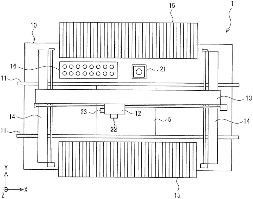
[0038] figure 1 It is a plan view showing the component mounting device according to the first embodiment of the present invention.

[0039] In the drawings, reference numeral 1 is a component mounting device. The component mounting apparatus 1 has a pair of conveyance rails 11 extending in the X direction on the upper surface of the base 10 . The transport rails 11 support both side edge portions of the circuit board 5 and are driven by a transport motor (not shown) to transport the circuit board 5 in the X direction.

[0040] In addition, the component mounting apparatus 1 has a mounting head 12 . The mounting head 12 has a plurality of suction nozzles for suctioning electronic components on its lower portion, and is configured to be horizontally movable in the XY direction on the base 10 by the X-axis gantry 13 and the Y-axis gantry 14 .

[0041] In this component mounting apparatus 1 , component supply devices 15 for supplying electronic components...

no. 2 Embodiment approach )

[0110] Next, a second embodiment of the present invention will be described.

[0111] In the above-mentioned first embodiment, after the board barcode B is recognized, the components are mounted sequentially from the first stop position, but in this second embodiment, the parts are mounted sequentially from the stop position after the board barcode B is recognized As for mounting components, since the structure of the component mounting device is the same as that of the above-mentioned first embodiment, description thereof will be omitted.

[0112] (structure)

[0113] Figure 9 It is a flowchart showing the flow of component mounting processing executed by the controller 30 in the second embodiment.

[0114] First, in step S41, the controller 30 judges whether or not the circuit board 5 is newly produced according to the production information stored in the memory. In addition, in the case of new production, the process proceeds to step S42, and in the case of continuation...


PUM


Abstract

The invention provides an element installation apparatus and a method thereof.A substrate barcode on a bar-shaped substrate is properly identified, The element installation apparatus (1) clamps a plurality of positions on a circuit substrate (5) along X direction, an electric element (20) is loaded at each stop position, before the element is loaded, the coordinate information of the substrate barcode (B) is obtained through a production programme, and the stop position of the substrate barcode (B) is identified employing a loading head camera (22). The circuit substrate (5) is clamped at the stop position, the substrate barcode is identified employing the loading head camera (22), and element loading action is performed at each stop position.

Description

technical field [0001] The present invention relates to a component mounting device and a component mounting method for mounting components supplied from a component supply device on a substrate. Background technique [0002] Conventionally, as a method of managing the mounting of electronic components on a mother board divided into a plurality of sub-boards, for example, the technique described in Patent Document 1 is known. This technology assigns a temporary ID to each sub-board, stores tracking information while mounting electronic components, replaces the temporary ID with a permanent identification ID, and prints a barcode or barcode representing the identification ID and tracking information. A mark composed of a QR code. This eliminates the need for a mark reading device, thereby reducing production costs and shortening man-hours. [0003] In addition, in the component mounting device, there may be cases where the area where the component can be mounted is overlapp...

Claims


Application Information

Patent Timeline
Patent Type & Authority Applications(China)
IPC IPC(8): H05K13/04
Inventor 宫本哲朗
Owner JUKI CORP
Why Eureka
Try Eureka