Supercharge Your Innovation With Domain-Expert AI Agents!

Drive device for vehicle

一种车辆驱动装置、动力传输机构的技术,应用在传动装置、动力装置、传动装置零件等方向,能够解决阻碍润滑等问题

Inactive Publication Date: 2013-09-25
AISIN AW CO LTD +1
View PDF5 Cites 30 Cited by
  • Summary
  • Abstract
  • Description
  • Claims
  • Application Information

AI Technical Summary

Problems solved by technology

However, this arrangement can make it difficult to supply oil to some of the gears, bearings, etc., which can prevent proper lubrication

Method used


Image

  • Drive device for vehicle
  • Drive device for vehicle
  • Drive device for vehicle

Examples


Embodiment Construction

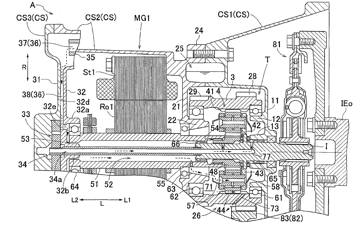
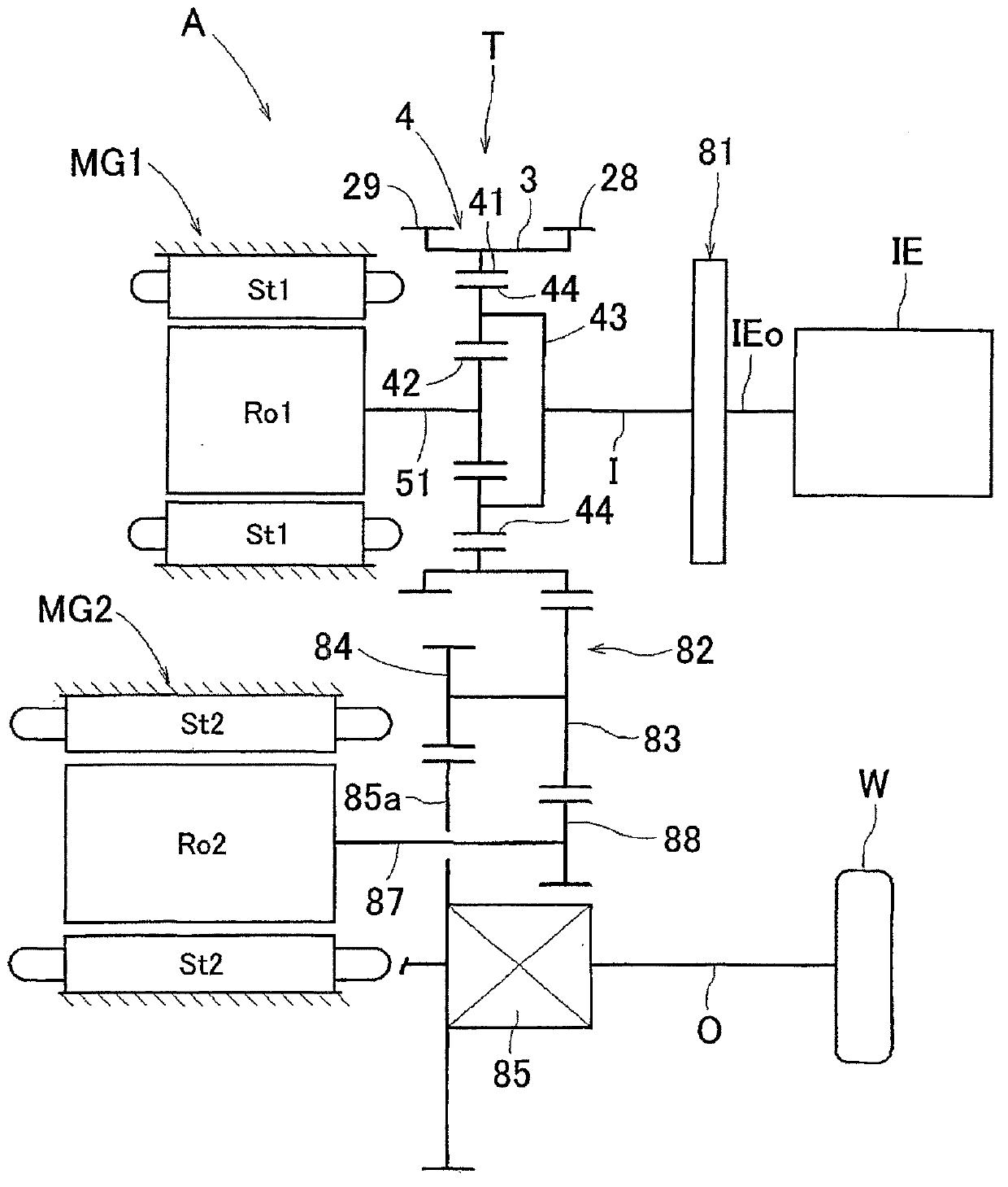
[0043] A vehicle drive device according to an embodiment of the present invention will be described with reference to the drawings. The vehicle drive device is a drive device for a hybrid vehicle including an internal combustion engine as a drive force source of wheels and at least one rotary electric machine. In this embodiment, the vehicle drive device A is formed as a drive device for a so-called two-motor split-type hybrid vehicle including an internal combustion engine IE as a drive force source for wheels W and two Rotating electrical machines MG1 and MG2. That is, the vehicle drive device A includes: an input shaft I drivably coupled to the internal combustion engine IE; a first rotary electric machine MG1 coaxial with the input shaft I arrangement; the second rotating electric machine MG2; the output shaft O, which is drivably coupled to the wheel W; and the power transmission mechanism T, which is drivably coupled to the input shaft I, the first The rotating electri...


PUM


Abstract

A drive device for a vehicle is achieved, the drive device being configured in such a manner that the axial dimension of the entire device is small and that each portion can be appropriately lubricated. A drive device (A) for a vehicle comprises, within a case shell (CS), an input shaft (I) connected to and driven by an internal combustion engine; a dynamo-electric machine (MG1); an output shaft connected to and driving wheels; and a power transmitting mechanism (T). The power transmitting mechanism (T) is provided with a cylindrical member (3) and an inner gear mechanism. The inner gear mechanism which meshes with the inner teeth (41) of the cylindrical member (3) is housed within an inner housing space (71), and the cylindrical member (3) is supported at both ends thereof in the axial direction by two support bearings (61, 62). The drive device also comprises: an oil storage section (25) capable of storing oil supplied by the rotation of the power transmitting mechanism (T); and a communication oil path (36) for connecting the oil storage section (25) and an inner peripheral space (52) within a rotor shaft (51). The rotor shaft (51) which is inserted and disposed in the inner housing space (71) has a supply communication hole (55) for connecting the inner peripheral space (52) and the inner housing space (71).

Description

technical field [0001] The invention relates to a vehicle drive comprising: an input shaft drivably coupled to an internal combustion engine; a rotating electrical machine; an output shaft drivably coupled to a wheel; A power transmission mechanism drivably coupling the input shaft, the electric rotating machine, and the output shaft; and a housing housing at least the electric rotating machine and the power transmission mechanism. Background technique [0002] A device disclosed in Patent Document 1 mentioned below is already well known as an example of the vehicle drive device described above. In the following description in the Background Art section, reference numerals and names used in Patent Document 1 are cited in parentheses as appropriate. As in Patent Document 1 Figure 4 As shown, in the device described in Patent Document 1, the ring gear (R) of the planetary gear mechanism (planetary gear unit 13) is coupled to a sleeve-shaped member ( The output shaft 14) rot...

Claims


Application Information

Patent Timeline
Patent Type & Authority Applications(China)
IPC IPC(8): B60K6/405F16H1/28F16H57/04F16H57/08B60K6/22B60K6/26B60K6/365B60K6/445B60L50/16
CPCB60K6/405B60K6/445F16H57/0424F16H57/043F16H57/0479F16H57/0486F16H3/727F16H2037/0866F16H2200/2005B60K6/365B60K6/48B60K2006/4825B60K2006/4833Y10T74/19056Y10S903/902Y02T10/62F16H37/065B60K6/22B60K6/26F16H1/28
Inventor 山本义久妹尾真充小松拓也佐田夏木矢田裕贵新智夫木村弘道桑原毅小畑达郎土田充孝森田吉则加藤真吾
Owner AISIN AW CO LTD
Features
  • R&D
  • Intellectual Property
  • Life Sciences
  • Materials
  • Tech Scout
  • Unparalleled Data Quality
  • Higher Quality Content
  • 60% Fewer Hallucinations
Learn More