On-demand power control system, on-demand power control system program, and computer-readable recording medium recorded with said program

A power control system and an on-demand technology, which are applied in the field of an on-demand power control system, a program of the on-demand power control system and a computer-readable recording medium recording the program, can solve the problem that the power reduction rate cannot be guaranteed, and no consideration is given to How much power to reduce, etc.

Inactive Publication Date: 2013-09-25
NITTO DENKO CORP
View PDF7 Cites 10 Cited by
  • Summary
  • Abstract
  • Description
  • Claims
  • Application Information

AI Technical Summary

Problems solved by technology

In this conventional type of HEMS, attention is paid to the use of electrical equipment, without considering how much power can be reduced by changing the use of each electrical equipment, and the power reduction rate that can meet the power saving request cannot be guaranteed.

Method used


Image

  • On-demand power control system, on-demand power control system program, and computer-readable recording medium recorded with said program
  • On-demand power control system, on-demand power control system program, and computer-readable recording medium recorded with said program
  • On-demand power control system, on-demand power control system program, and computer-readable recording medium recorded with said program

Examples


no. 1 approach

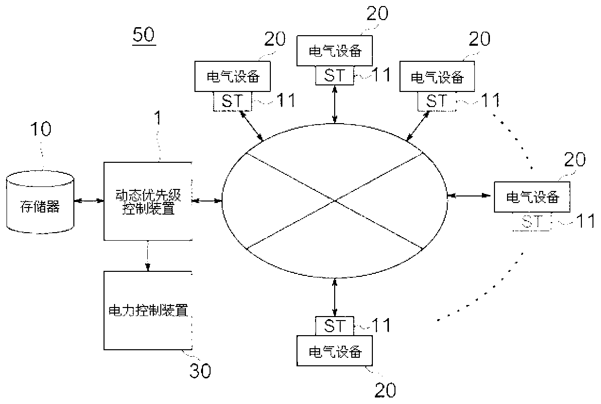
[0142] Figure 8 yes means figure 1 A functional block diagram of the first embodiment showing the functions of the priority device.

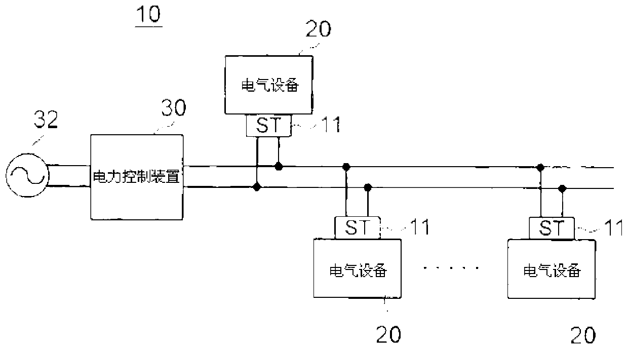
[0143] Figure 8 Reference numeral 1 denotes a priority device, reference numeral 10 denotes its memory, and reference numeral 11 denotes ST, which is composed of an initial target value updating unit 120 and a power mediation unit 122 . Reference numeral (1) denotes power consumption transmitted from ST. Furthermore, prior to its operation, the priority device converts the above-mentioned power consumption into a power usage plan for determining power usage at every minimum control interval τ as preprocessing, and the power usage plan, the instantaneous power of the initial target value, and the maximum instantaneous power stored in memory 10. Reference numeral (2) denotes a power request message sent from the ST, which is sent to the power mediation unit 122 described above.

[0144] Furthermore, the initial target value updating unit 12...

no. 2 approach

[0224] The above-mentioned dynamic priority control unit 1 can finally control the instantaneous power to be below the maximum instantaneous power, and can perform control that satisfies the upper limit value C (Wh) of the accumulated electric power. An increase in instantaneous power such that the maximum instantaneous power is sometimes exceeded. A second embodiment to cope with this situation will be described.

[0225] Figure 16 is a functional block diagram of the second embodiment.

[0226] The priority device includes an initial target value update unit 120 , a power mediation unit 122 and a continuous monitoring unit 124 .

[0227] The initial target value update unit 120 and the electric power mediation unit 122 have the same functions as those of the above-mentioned units, so the description thereof will be omitted.

[0228] The continuous monitoring unit 124 continuously monitors the power consumption, and when the overall power consumption exceeds the maximum i...


PUM


Abstract

The purpose of the present invention is to be able to control the supply of power of a commercial power source in real time in relation to the power request needed by a user and to control the supply of power matching the QoL the user needs in daily life. The dynamic priority control device of the present invention is characterized by being provided with an initial target value updating means and a power arbitration means. The initial target value updating means calculates an updated initial target value by distributing the difference between the instantaneous power of the initial target value and the actual instantaneous power to the instantaneous power of the subsequent initial target value, and compares said updated initial target value with a maximum target value. If the aforementioned updated initial target value is smaller than the maximum instantaneous power, the initial target value updating means updates the instantaneous power of the subsequent target value as the updated initial target value. Meanwhile, if the updated initial target value is greater than the maximum instantaneous power, the initial target value updating means updates the instantaneous power of the initial target value to the maximum instantaneous power and sets said value as the updated initial target value. The power arbitration means calculates the total value of the consumption power of electronic devices in operation, calculates the priority of both electronic devices on the basis of a set of electronic device characteristic class data, and compares the consumption power total value with the updated initial target value. If the consumption power total value is smaller than the updated initial target value, the power arbitration means supplies power to the transmitted electronic devices. Meanwhile, if the consumption power total value is greater than the updated initial target value, the power arbitration means selects an electronic device having the lowest priority by calling the priorities from the memory, determines the nature of the feature of the electronic device by referring to the abovementioned class data, and performs arbitration on the basis of the priorities among the electronic devices.

Description

technical field [0001] The present invention relates to an on-demand power control system in a home or office network, a program for the on-demand power control system, and a computer-readable recording medium recording the program. (Quality of Life) (hereinafter referred to as "QoL") to dynamically change the priority among electrical equipment and control the power supply without exceeding the upper limit of power consumption (Wh), on-demand A type electric power control system program and a computer-readable recording medium recording the program. Background technique [0002] The on-demand power control system is a system for realizing energy management in homes and offices. "pull" system. This system is a system that infers "which request from the device is the most important" from the home server according to the user's utilization method for power requests from various home appliances, that is, devices, such as air conditioners, lighting, etc., and according to the ...

Claims


Application Information

Patent Timeline
Patent Type & Authority Applications(China)
IPC IPC(8): G06Q50/06
CPCG06Q50/06Y02B70/3225Y04S20/222H04L12/2827H02J2310/14H02J3/14H02J13/00H02J3/00Y04S20/242Y02B70/30Y04S20/20H02J4/00
Inventor 松山隆司加藤丈和汤浅健史
Owner NITTO DENKO CORP
Why Eureka
Try Eureka