Chamfering and cutting flame trolley

A flame and trolley technology, which is applied in the field of chamfering and cutting flame trolleys, can solve problems such as difficulty in chamfering cutting of thin plates, and achieve the effect of easy promotion and simple structure.

Inactive Publication Date: 2013-10-02
中船桂江造船有限公司
View PDF9 Cites 7 Cited by
  • Summary
  • Abstract
  • Description
  • Claims
  • Application Information

AI Technical Summary

Problems solved by technology

[0007] The purpose of the present invention is to provide a magneto-hydraulic directional control valve, which solves the problem that the existing cutting device is difficult to chamfer the thin plate and can only perform straight-line cutting.

Method used


Image

  • Chamfering and cutting flame trolley

Examples


Embodiment 1

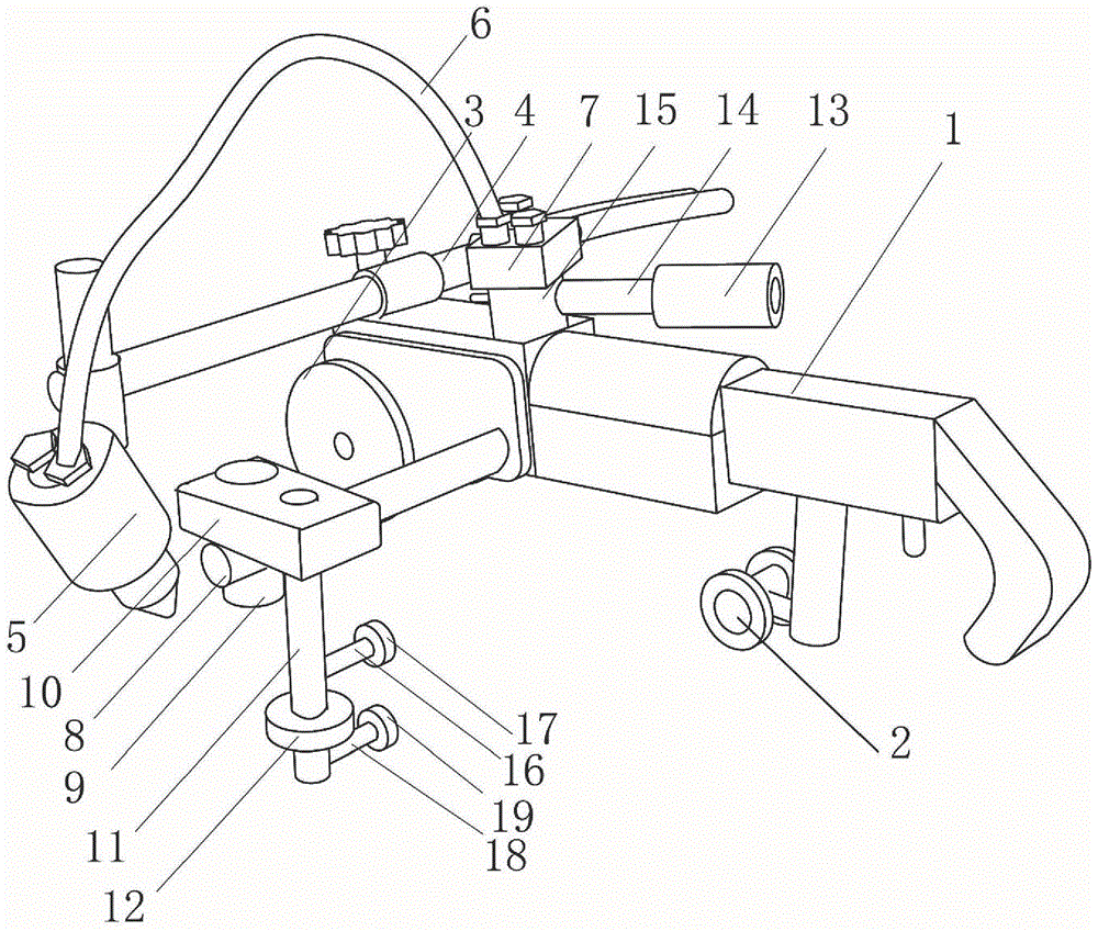
[0022] Such as figure 1 As shown, the chamfering cutting flame trolley includes flame gas cutting machine main body 1, universal wheel 2, road wheel 3, tail adjustment rod 4 and flame nozzle 5, universal wheel 2 and road wheel 3 are respectively installed on the flame gas cutting machine body 1, the front and the rear of the tail adjusting rod 4 are connected to the main body of the flame gas cutting machine 1 at one end, and the flame nozzle 5 is installed at the other end. A rotating part 15 is arranged under the air pump 7, and one end of the counterweight slide bar 14 is fixedly connected with the rotating part 15, and the other end is provided with a counterweight part 13. The side part of the main body 1 of the flame cutting machine is fixedly connected with one end of the side connecting rod 8, and the other end of the side connecting rod 8 is connected to the guide clamping part 10 through the side lifting rod 9, and the guide clamping part 10 is also provided with a g...

Embodiment 2

[0025] The difference from Example 1 is that a 6mm thick curved steel plate edge is used for 30-degree chamfering. The experimental steel plate edge has an arc length of 12 meters, a radius of 8 meters, and an arc of 70 degrees. The chamfering and cutting work is completed in about 7 minutes. .

Embodiment 3

[0027] The difference from Example 1 is that a 12mm thick curved steel plate edge is used for 30-degree chamfering. The experimental steel plate edge has an arc length of 11 meters, a radius of 8 meters, and an arc of 80 degrees. The chamfering and cutting work is completed in about 6 minutes. .


PUM


Abstract

The invention discloses a chamfering and cutting flame trolley, comprising a flame gas cutting machine main body (1), a universal wheel (2), traveling wheels (3), a tail adjusting rod (4) and a flame sprayer (5), wherein the universal wheel (2) and the traveling wheels (3) are respectively mounted on the front part and the rear part of the flame gas cutting machine main body (1); one end of the tail adjusting rod (4) is connected with the flame gas cutting machine main body (1); and the other end of the tail adjusting rod (4) is provided with the flame sprayer (5) which is connected with a gas delivery pump (7) on the flame gas cutting machine main body (1) through a gas delivery pipe (6). The chambering and cutting flame trolley is characterized in that a side connecting rod (8) is fixed on the side, with the flame sprayer (5), of the flame gas cutting machine main body (1); and the side connecting rod (8) is connected with a guide clamping piece (10) through a side lifting rod (9). According to the chamfering and cutting flame trolley, a guide wheel is added on the side part of a flame gas cutting machine, so that the edges of arc-shaped, S-shaped and semi-circular plates can be chambered by the flame trolley.

Description

technical field [0001] The invention relates to a chamfering and cutting tool, in particular to a chamfering and cutting flame trolley. Background technique [0002] The general processing methods in shipyards are divided into cold and hot processing. Cold processing mainly includes flattening, shearing, punching, rolling, folding, planing, etc., and hot processing mainly includes gas cutting and hot bending. Among them, planing has a great influence on the welding quality of the hull, mainly affecting its appearance shaping and deformation control. According to the requirements of the plate welding technical parameters, it is necessary to do welding groove treatment for plates with a thickness of 6mm or more, and the treatment of the groove mainly includes mechanical processing and flame cutting. [0003] Under the current technical situation, when the plate size is 6mm-12mm, the outer plate of the ship and the plate with linear curvature are cut by a semi-automatic cuttin...

Claims


Application Information

Patent Timeline
Patent Type & Authority Applications(China)
IPC IPC(8): B23K7/00B23K7/10
Inventor 黄永忠黎锵民赖建国庞文
Owner 中船桂江造船有限公司
Why Eureka
Try Eureka