
Ball guiding device for bearing steel ball

A bearing steel ball and guide ball technology, which is applied in the direction of transportation and packaging, conveyor objects, etc., can solve the problems of bearing steel ball extrusion, affecting the quality of bearing steel balls, wear and deformation, etc.

Inactive Publication Date: 2013-10-02
WUXI MINGZHU STEEL BALL
View PDF6 Cites 2 Cited by
  • Summary
  • Abstract
  • Description
  • Claims
  • Application Information

AI Technical Summary

Problems solved by technology

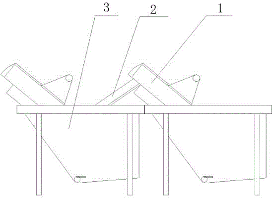
[0002] Whether the quality of the bearing is good or not, the bearing steel ball plays a big role. In order to reduce the bearing noise caused by the shaking of the bearing steel ball in the bearing, the bearing steel ball needs to have higher roundness and smoothness, and the bearing steel ball During the processing and production process, it is necessary to clean the processed and formed bearing steel balls. Usually, the bearing steel balls are cleaned by the ball washing machine first, and then cleaned by oil return, dehydration oil and anti-rust oil. steps, see figure 1 , in the automatic cleaning production line of bearing steel balls, the bearing steel balls are transported by the conveyor 1. When the steel balls automatically enter the next cleaning process, the existing conveying method is usually to use the inclined plane conveying guide groove 2 to transport the bearing steel balls smoothly Entering the next cleaning device 3, since the bearing steel balls are conveyed in batches during the cleaning of the bearing steel balls, the bearing steel balls will be squeezed during the conveying process, the longer the distance of the conveying guide groove, the probability of the bearing steel balls being squeezed and deformed The larger the bearing steel ball is, the more likely it is to cause the bearing steel ball to be squeezed, worn and deformed by conveying the bearing steel ball through the inclined plane conveying guide groove, which affects the quality of the bearing steel ball and reduces the yield of the bearing steel ball

Method used


Image

  • Ball guiding device for bearing steel ball
  • Ball guiding device for bearing steel ball
  • Ball guiding device for bearing steel ball

Examples


Embodiment Construction

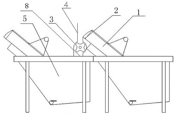
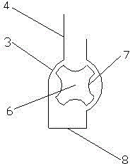
[0015] see figure 2 and image 3 , a ball guide device for bearing steel balls, which includes a conveyor 1, the lower end of the ball outlet 2 of the conveyor 1 is vertically provided with a conveying wheel 3, the conveying wheel 3 is a cylinder placed horizontally, with upper and lower openings, and the interior of the conveying wheel 3 There is a ball guide wheel 6 coaxial with it, and the ball guide wheel 6 is evenly distributed with grooves 7 in the transverse direction. The ball guide wheel 6 is connected to a motor and rotates reversely under the drive of the motor.

[0016] The working process of the ball guide device of the bearing steel ball of the present invention is as follows:

[0017] After the bearing steel ball passes through the conveyor 1, it falls into the conveying wheel 3 from the ball outlet 2. When the groove on the guide wheel 6 turns to the opening of the conveying wheel 3, the bearing steel ball enters the groove and rotates counterclockwise until ...


PUM


Abstract

The invention provides a ball guiding device for a bearing steel ball. The ball guiding device comprises a conveyor (1) and a conveying wheel (3) which is vertically arranged on the lower end of the ball outlet port (2) of the conveyor (1), the conveying wheel (3) is a cylindrical body which is transversely placed, the conveying wheel is opened at the upper and lower parts, a ball guiding wheel (6) which is coaxially arranged with the conveying wheel is arranged inside the conveying wheel (3), grooves (7) are uniformly distributed on the transverse direction of the ball guiding wheel (6), and the ball guiding wheel (6) is connected with a motor to rotate under the drive by the motor. By adopting the structure, since the conveying wheel is arranged on the lower end of the ball outlet port of the conveyor, each groove carrying one bearing steel ball enters into the next cleaning process, the extrusion, the abrasion and the deformation occurring in the conveying process of the bearing steel ball are effectively prevented, the quality of the bearing steel ball is ensured, and the finished rate of the bearing steel ball is improved.

Description

technical field [0001] The invention relates to the technical field of bearing steel ball production, in particular to a ball guide device for bearing steel balls. Background technique [0002] Whether the quality of the bearing is good or not, the bearing steel ball plays a big role. In order to reduce the bearing noise caused by the shaking of the bearing steel ball in the bearing, the bearing steel ball needs to have higher roundness and smoothness, and the bearing steel ball During the processing and production process, it is necessary to clean the processed and formed bearing steel balls. Usually, the bearing steel balls are cleaned by the ball washing machine first, and then cleaned by oil return, dehydration oil and anti-rust oil. steps, see figure 1 , in the automatic cleaning production line of bearing steel balls, the bearing steel balls are transported by the conveyor 1. When the steel balls automatically enter the next cleaning process, the existing conveying me...

Claims


Application Information

Patent Timeline
IPC IPC(8): B65G47/34
Inventor 吴昊
Owner WUXI MINGZHU STEEL BALL
Learn More