
Scum treatment device of aerated grit chamber

A technology for aeration, sand settling and treatment equipment, which is applied in the direction of flotation water/sewage treatment, feeding/discharging device of settling tank, flocculation/sedimentation water/sewage treatment, etc. It can solve problems such as scum cannot be removed, Achieve the effect of eliminating oil residue, less failure and stable operation

Inactive Publication Date: 2013-10-02
温州市环境发展有限公司
View PDF6 Cites 12 Cited by
  • Summary
  • Abstract
  • Description
  • Claims
  • Application Information

AI Technical Summary

Problems solved by technology

[0010] The present invention completely solves the problem that the scum in the "dead zone" cannot be removed through the double slag scraper that can be controlled to lift, and effectively reduces the operation failure of the equipment

Method used


Image

  • Scum treatment device of aerated grit chamber
  • Scum treatment device of aerated grit chamber
  • Scum treatment device of aerated grit chamber

Examples


Embodiment Construction

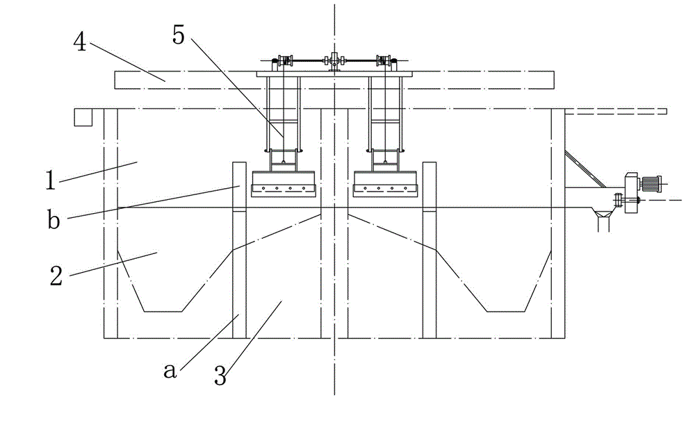
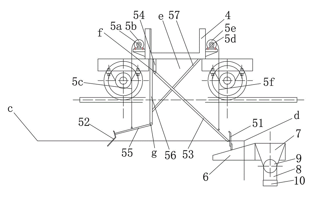
[0020] Such as figure 1 , figure 2 Shown, the aerated grit chamber scum treatment device embodiment of the present invention,

[0021]Including aeration grit chamber 1, the bottom of aeration grit chamber 1 is slope-shaped, aeration grit chamber 1 is divided into aeration grit chamber 2 and oil and slag removal area 3, aeration grit chamber 2 and removal Barrier a and partition b are arranged between the oil scraping area 3. Partition b and bar a are vertically arranged in a straight line and partition b is located above bar a. The top of partition b is higher than the pool surface and the bottom of bar a is connected to the pool In this way, the sand and gravel can be blocked at the bottom of the aerated grit chamber 2 and the oil residue will enter the oil removal and scraping area 3 through the grid bar a and float on the pool surface. The aerated grit chamber 1 has a sand suction bridge 4, The sand-absorbing bridge 4 is suspended above the aerated grit chamber 1 and mov...


PUM


Abstract

The invention provides a scum treatment device of an aerated grit chamber, which is obvious in scum scraping effect, runs stably, is high in efficiency, and has less faults. The scum treatment device of the aerated grit chamber comprises an aerated grit chamber, wherein the aerated grit chamber is provided with a grit absorption bridge; the grit absorption bridge is suspended above the aerated grit chamber and moves linearly back and forth along the trend of the aerated grit chamber; the linear moving path of the grit absorption bridge is provided with an initial end close to a water intake part of the aerated grit chamber and a tail end close a water drainage part of the aerated grit chamber; the grit absorption bridge is provided with a grit absorption pump acting on the bottom of a chamber of an aerated grit zone as well as a scum scraping device acting on a chamber surface of an oil removing and scum scraping zone; the scum scraping device comprises a scum scraping plate and a pre-scraping plate which can be installed on the grit absorption bridge at the same time in a lifting mode, are respectively distributed on the chamber surfaces of the oil removing and scum scraping zone along the motion direction of the grit absorption bridge back and forth, and are respectively positioned at the outer side of a space below the grit absorption bridge; when the grit absorption bridge is positioned on the initial end of the linear moving path, the pre-scraping plate is fit to the chamber surface of the water intake part of the grit absorption bridge; when the grit absorption bridge is positioned on the tail end of the linear moving path, the scum scraping plate is fit to the chamber surface of the water drainage part of the aerated grit chamber.

Description

technical field [0001] The invention relates to the facilities in the sewage treatment process, in particular to the scum treatment device of the aeration grit chamber. Background technique [0002] The existing aeration grit chambers are divided into two grids, one is an aeration grit chamber, and the other is an oil removal and slag removal area, and the two groups are separated by vertically arranged rectification bars. In the sand settling area, the vertical water flow forms a spiral flow due to the injection of compressed air, and the sand with a large specific gravity sinks to the bottom of the tank, and is transported to the sand-water separator by the sand suction pump. Fat, oil, scum, etc. As a result, it floats to the water surface and enters the oil removal and scum scraping area. The scum scraper fixed on the sand suction bridge scrapes the scum to the scum tank. [0003] There is following defect in above-mentioned existing aerated grit chamber: [0004] (1) ...

Claims


Application Information

Patent Timeline
Patent Type & Authority Applications(China)
IPC IPC(8): C02F1/52C02F1/24C02F1/40B01D21/02B01D21/24B01D29/03
Inventor 廖建胜李文兴甘大生彭毅张思李丕拳夏奇祥薛晓鹏叶浩然林书铮
Owner 温州市环境发展有限公司
Learn More