Device and method for underground coal mine hydraulic slit cutting self-suction type material abrading jet flow generation

A hydraulic cutting and abrasive jet technology, which is applied in the direction of mining fluid, earth drilling, wellbore/well parts, etc., can solve the problems of poor cutting effect and insufficient cutting ability of pure water jet, and achieve simple structure and high efficiency. Optimum, low drag loss effect

Active Publication Date: 2013-10-02
CHONGQING UNIV
View PDF7 Cites 14 Cited by
  • Summary
  • Abstract
  • Description
  • Claims
  • Application Information

AI Technical Summary

Problems solved by technology

[0004] The purpose of the present invention is to overcome the shortcomings of the prior art, to provide a coal mine underground hydraulic slotting sel

Method used


Image

  • Device and method for underground coal mine hydraulic slit cutting self-suction type material abrading jet flow generation
  • Device and method for underground coal mine hydraulic slit cutting self-suction type material abrading jet flow generation
  • Device and method for underground coal mine hydraulic slit cutting self-suction type material abrading jet flow generation

Examples


Embodiment Construction

[0023] The present invention will be further described below by means of the accompanying drawings and examples.

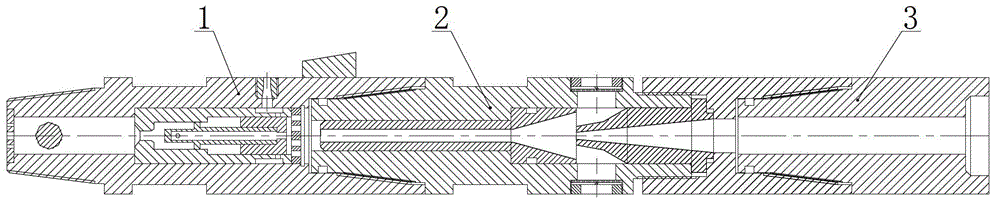
[0024] combine Figure 1 to Figure 3 , the implementation of the hydraulic slotting self-priming abrasive jet generating device used in underground coal mines is now described:

[0025] The coal mine underground hydraulic slotting self-priming abrasive jet generating device includes a front-end slotting device 1 and a self-priming device 2 .

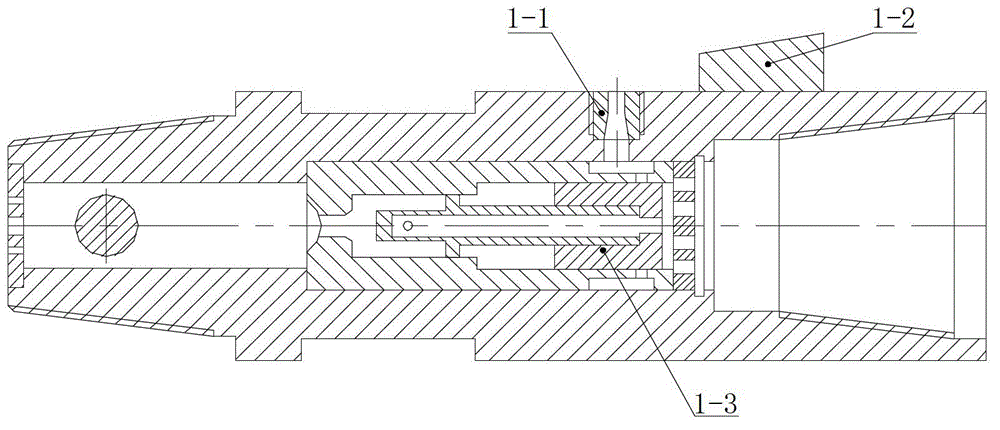
[0026] combine figure 2 It can be seen that the front end slotter 1 is a hollow structure that runs through front and back, and radial nozzles 1-1 are installed in the radial direction, which are jet flow generating devices. The reversing valve core 1-3 is installed in the middle of the slit device. When the water pressure reaches the threshold value of the reversing spool, the radial water hole on the reversing spool is opened, and the radial nozzle is connected with the slit device, and the slit device Enter the workin...


PUM


Abstract

A device for underground coal mine hydraulic slit cutting self-suction type material abrading jet flow generation comprises a front end slit cutter and a self-suction device. The self-suction device is composed of a cavity, a throat pipe located in the cavity, an inlet nozzle and an end cover, wherein the inlet nozzle and the end cover are located at the rear end of the cavity. The throat pipe is installed on the front portion inside the cavity, the front end of the throat pipe is an accelerating cavity, and the rear end of the throat pipe is a suction cavity. The inlet nozzle is arranged on the rear portion of the cavity, an outlet formed in the front end of the inlet nozzle faces the center of the rear end of the throat pipe, and the diameter of the front end of the inlet nozzle is smaller than the caliber of a horn opening of the rear end of the throat pipe. A suction hole is formed in the wall of the cavity in the radial direction. The peripheral space passing through the outlet formed in the front end of the inlet nozzle is identical to that of the horn opening of the rear end of the throat pipe. A filter device is arranged inside the suction hole. A slit cutter connecting structure is arranged on the outer wall of the front end of the self-suction device and connected with the front end slit cutter. The rear end of the slit cutter connecting structure is connected with the end cover and provided with a drilling rod connecting end. According to the device for underground coal mine hydraulic slit cutting self-suction type material abrading jet flow generation, coal particles generated by slit cutting can enter the inner side of the self-suction device after being screened by a filter screen, the coal particles are sprayed out through a radial nozzle after being fully mixed, so that rear mixed type material abrading jet flow is formed, the depth and the width of a hydraulically-cut groove are increased, hard coal and gangue can be cut, and the slit cutting effect is remarkably improved.

Description

technical field [0001] The invention relates to the coal mine underground hydraulic slotting technology, in particular to the self-priming abrasive jet generation technology. Background technique [0002] Gas drainage is one of the most effective methods to control coal mine gas disasters. "Draining first and then mining" is the policy of gas control in my country. But at present, most mines in our country belong to low-permeability coal seams, and the gas extraction rate is low, which cannot meet the increasing mining requirements, and seriously restricts the mining and production work of mines. Underground coal mine hydraulic slotting uses high-pressure water jets to cut radially at fixed points within the coal seam range of the extraction borehole or cut up and down within the coal seam range. After cutting, a deep flat slot is formed around the borehole, and the cutting is cut The coal slag that comes down is brought out of the hole, thereby increasing the exposed area ...

Claims


Application Information

Patent Timeline
IPC IPC(8): E21B43/114
Inventor 葛兆龙卢义玉周哲夏彬伟程亮汤积仁梅绪东张欣玮
Owner CHONGQING UNIV
Why Eureka
Try Eureka